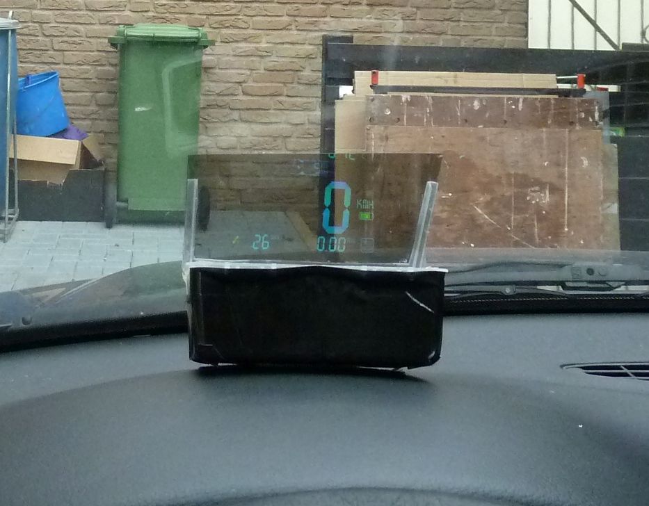
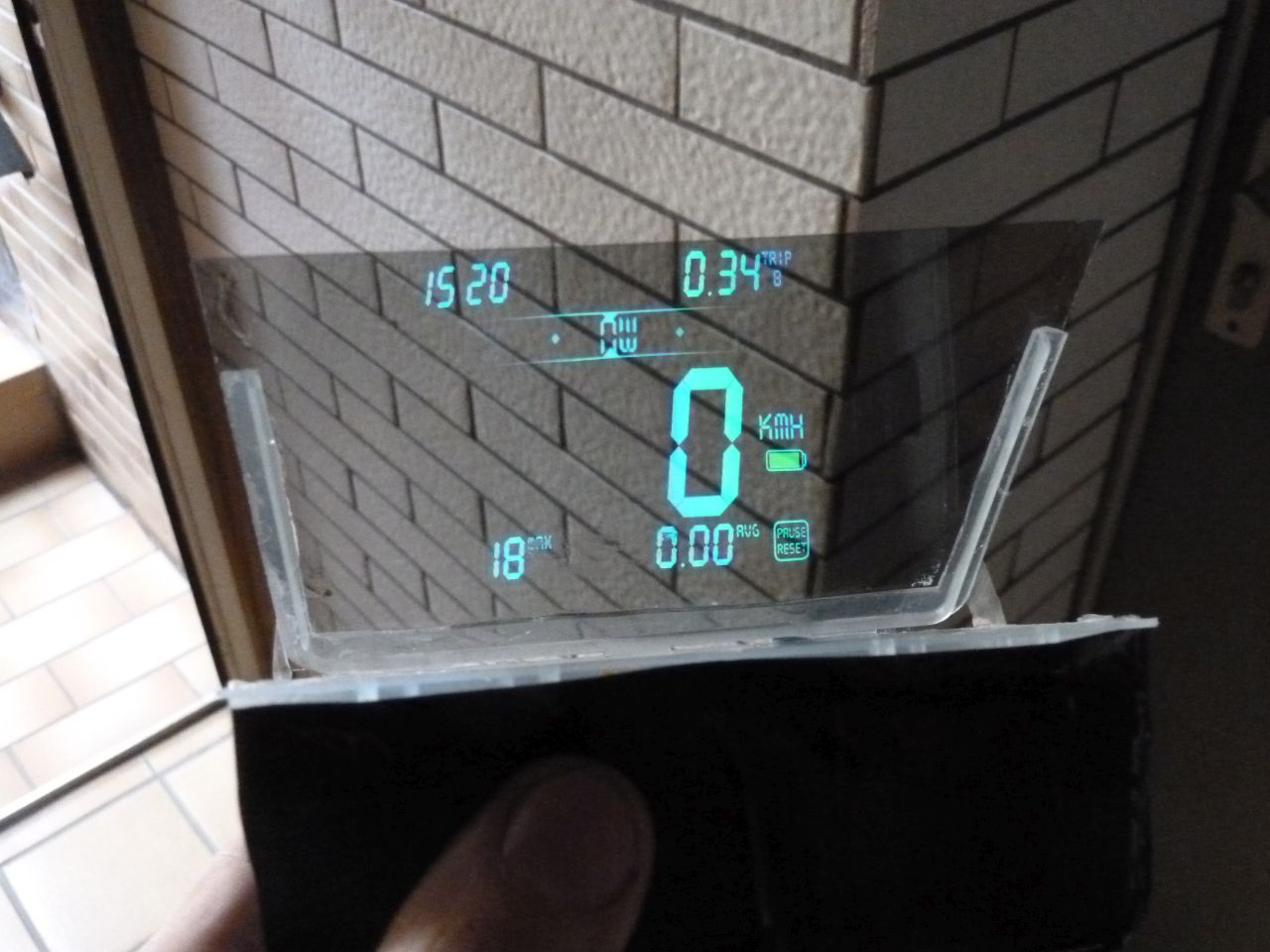
Ingredients:
- Android phone
- reflector film (from an old TFT display)
- Android HUD software
…and you have something really cool in your car 😉
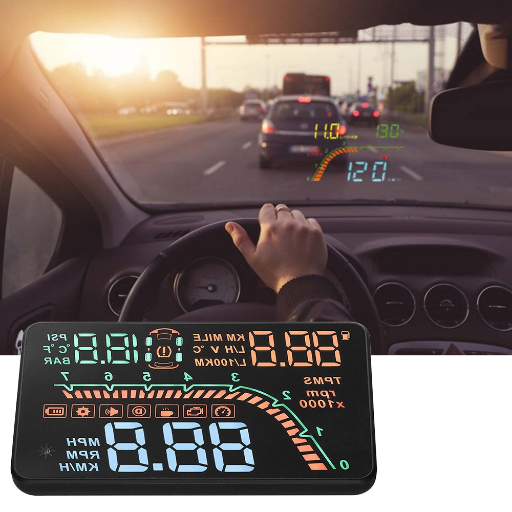
Results by commercial OBD-based HUD products:
Ingredients:
…and you have something really cool in your car 😉
Results by commercial OBD-based HUD products:
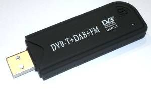
Ein USB-DVB-T Stick (mit R820T-Tuner und RTL2832U-Demodulator) schickt über eine externe Antenne empfangene Signale im Bereich von ca. 50 Mhz bis ca. 1800 Mhz (ggf. sogar höher) zum PC. Mit einer passenden Software kann man das Signal im Zeit- oder Frequenzbereich untersuchen und sich so z.B. das Spektrum des Signals ansehen.
Funktionsweise:

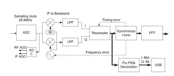
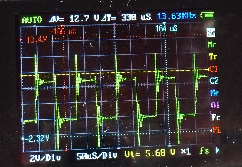
Der Tuner (R820T) empfängt das RF-Signal und schickt es über Vorverstärker (Low Noise Amplifier/LNA), Power Detector (pdet), Bandpaß-Filter und ‘Image Rejection Filter’ (RF_Filter). Der Mischer konvertiert das RF-Signal zu einer niedrigeren Zwischenfrequenz (Intermediate Frequency/IF), welche von der Anwendungs-Bandbreite abhängt. Die Standard IF-Filter implementieren 6/7/8 Mhz Bandbreiten. Über einen Ausgangsverstärker mit variabler Verstärkung (Variable Gain Amplifier, VGA) wird das Signal in den Analog-Digital-Wandler (ADC) geschickt.
Über einen Analog-Digital-Wandler (ADC) wird das analoge Signal gesampelt und als Quadratursignal (I-Q-Signal, d.h. Q=asin(Phase)*Amplitude, I=acos(Phase)*Amplitude) kodiert (Orthogonales Frequenzmultiplexverfahren/COFDM). Da der ADC-Takt höher liegt als die Symbol-Rate, führt ein Resampler die Konvertierung in Symbol-Rate durch. Das Ausgangssignal wird über USB ausgelesen.
Technische Daten:
Tuner: Rafael Micro R820T
Demodulator: Realtek RTL2832U
Verwendete Software:
Linux: Gqrx SDR, RTL_SDR_Wide_Spectrum_Analyzer, …
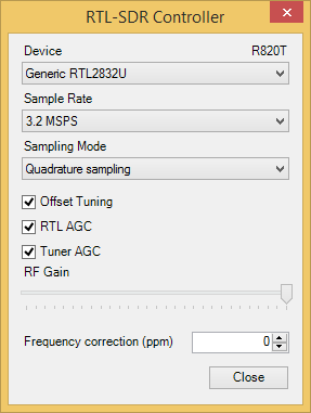
Windows: Die verwendete Software (SDR#) kann das gesuchte Signal im Frequenzbereich darstellen, demodulieren (FM, AM etc.) und über PC-Lautsprecher ausgeben:

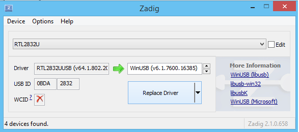
Wichtig: nicht den Original-Treiber des Sticks verwenden- SDR# enthält das Programm “zadig” womit der passende Treiber installiert wird:
Einige Frequenzen/Signale sind erst nach Änderung der Einstellungen (Sample Rate, RTL/Tuner AGC), zu empfangen:
Beispiele:
433 Mhz Sender:

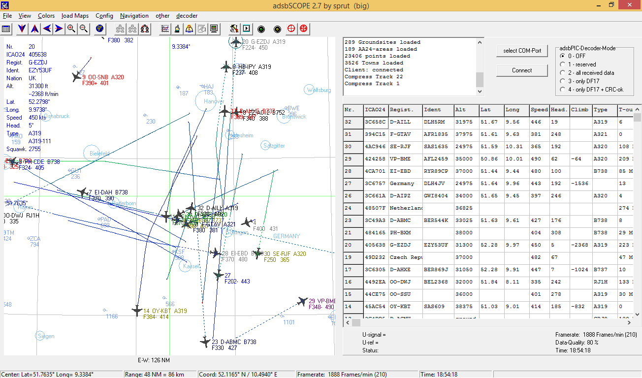
1090 Mhz Flugradar (Reichweite ca. 300 km)
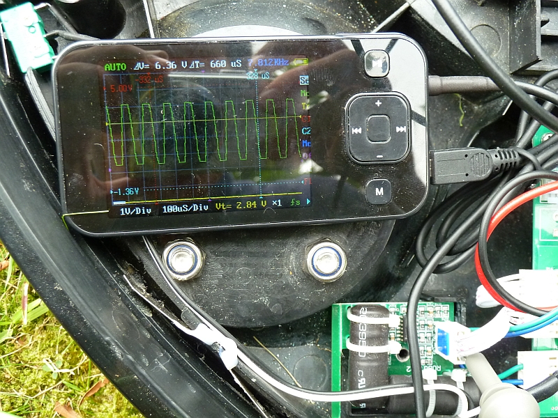
1,8 Ghz DECT Telefon einschalten – Man sieht die Kommunikation vom Telefon mit der Basisstation: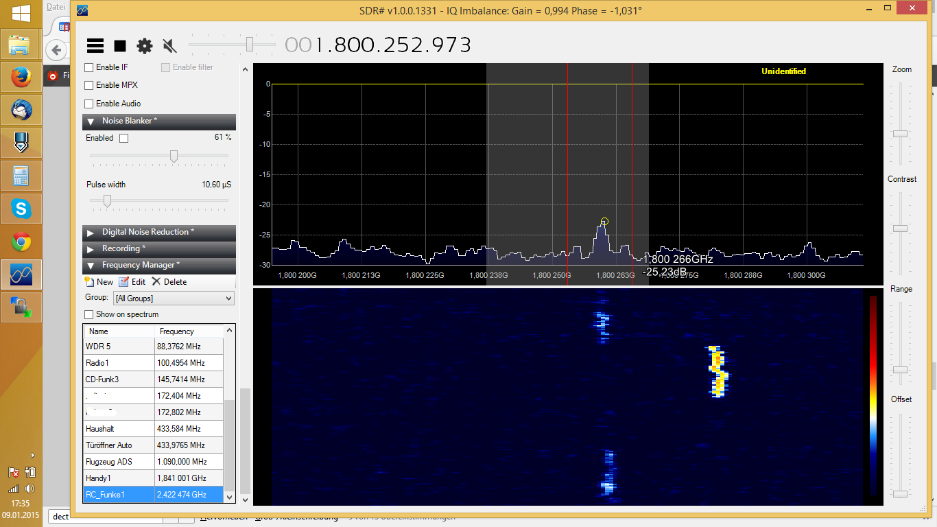
2,4 Ghz Funke:

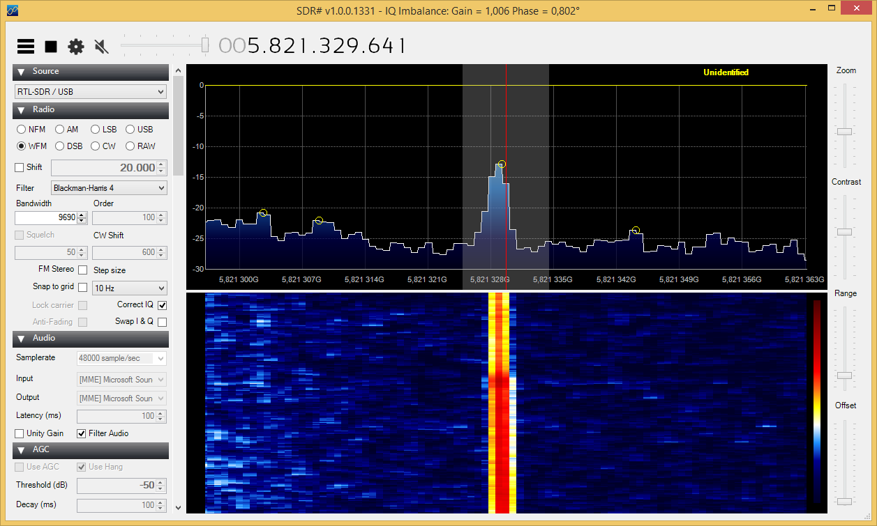
5,8 Ghz Video Transmitter:
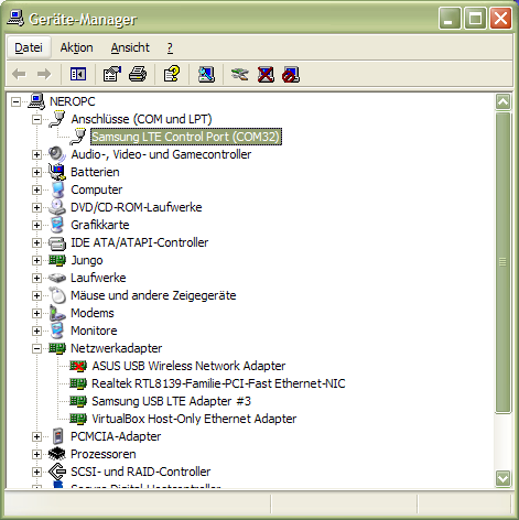
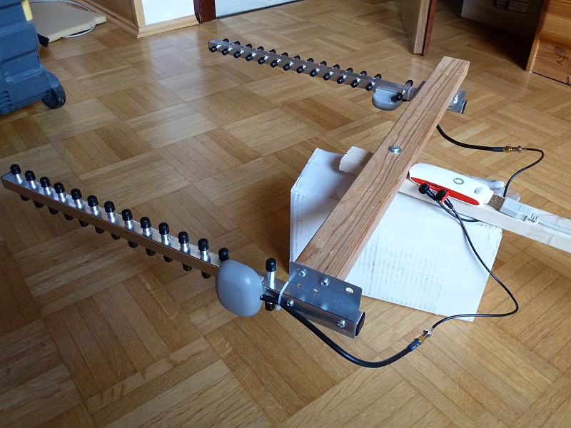
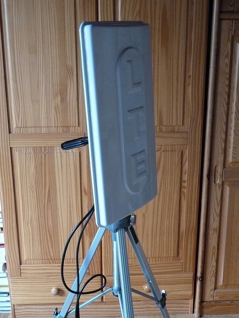
Zum Ausrichten einer externen LTE Richtantenne reicht die (grobe und langsame) Anzeige der Signalstärke in der Verbindungssoftware oft nicht aus. Mit einem Trick kann man sich die Signalstärke in einem Terminal-Programm genauer anzeigen lassen. Getestet wurde dies mit einem Vodafone K5005 4G/LTE USB Stick (ein Huawai E398) und einem Vodafone Samsung GT-B3740 4G/LTE USB Stick.
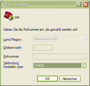
Die Verbindung sollte nun geöffnet werden und das Modem liefert dann fortlaufend Informationen zur Signalstärke. Das Huawai-Modem liefert beispielsweise fortlaufend die Werte RSSI und RSRP.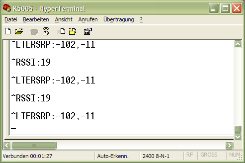
Beispielmessung an verschiedenen Standorten:
              RSSI    RSRP

Wohnzimmer    25      -87, -8
Balkon        28      -83,-11
Beim Samsung muss zunächst manuell über die Tastatur “AT+MODESELECT=2” (+ENTER) eingeben werden, damit die Signalstärke fortlaufend ausgegeben wird. Alternativ kann man mit “AT+CSQ” (+ENTER) die Signalstärke einmalig abfragen.
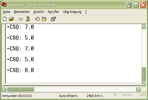
CSQ: Indikator für Empfangssignalstärke (0 bis 31 )
0=schlecht ( < -113 dB)
31=beste (> – 51 dB)
Falls man den CSQ-Wert in dBm umrechnen möchte, kann man das mit folgender Formel machen:
dBm = -113 + CSQ * 2 (Beispiel: CSQ=20 ergibt dBM=-73)
Anhand dieser Werte kann man nun seine externe Richtantenne ausrichten.
Viel Erfolg!
PS: Mit der Vodafone LTE TurboBox (Modem) soll es einen ähnlichen Weg geben, um die exakte Signalstärke auslesen zu können (siehe Vodafone-Forum). Dort wird über ein virtuelles LAN (VLAN) eine Verbindung über Telnet aufgebaut und hierüber dann das Kommando zum Abfragen der Signalstärke geschickt (AT%LG_STS).
-Arduino Version-
Update 2015: I developed an Arduino OBD reader for the older OBD KW1281 protocol:
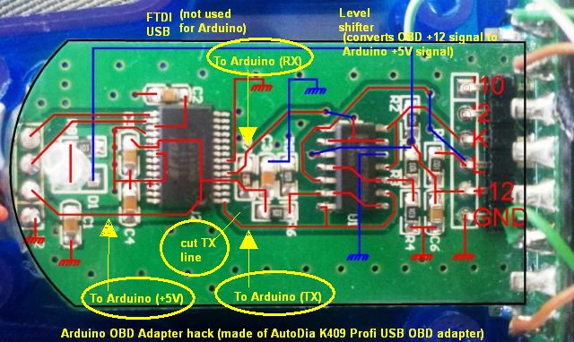
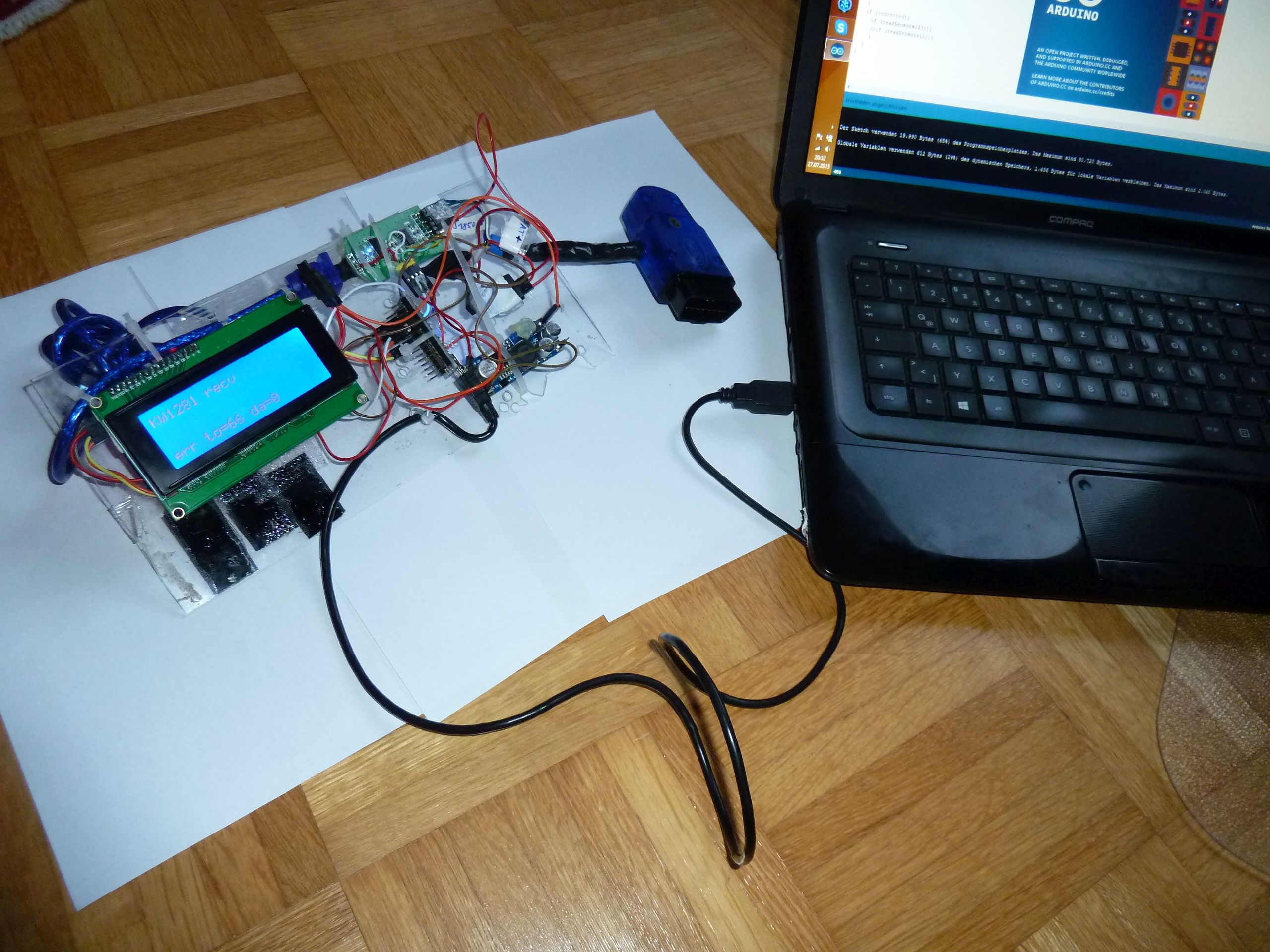

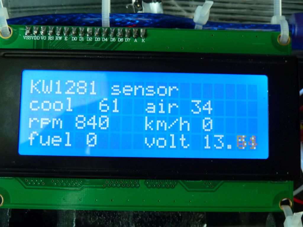
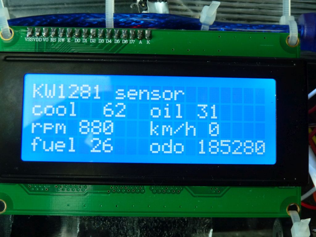
Download Arduino Code for the KW1281 OBD protocol: arduino_kw1281
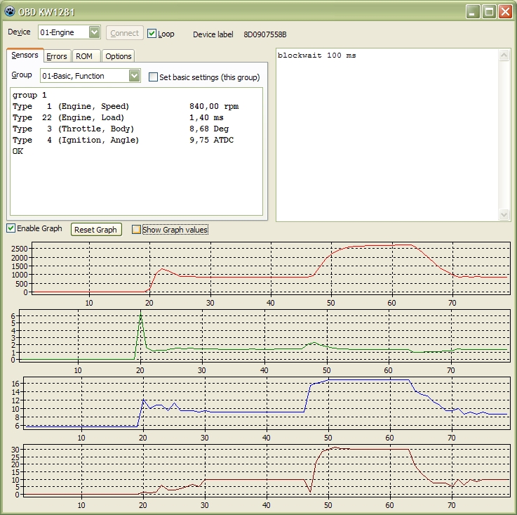
-PC Version-
My Audi A4/B5 (1997) and many other old cars use the older OBD KW 1281 protocol – I tried to find any suitable OBD software for my car to speak to my motor and dashboard control units (ECU), however:
So, using the KW1281 protocol, the correct initialization timing (baud 5) is critical, and some software does not wait before waking up the ECU. Finally, I decided to develop something on my own. Note: my software only supports the older KW1281 protocol!
Features of my KW1281 diagnostic software:
What you need:
Screenshot:
Download:
obd_kw1281 (executable)
obd_kw1281 (freepascal_lazarus code)
Please send me your feedback! Thanks 🙂 If you send your feedback, please always send me the complete debug output.
My car’s OBD data:
- Audi A4 B5 1.8, 1997, ADR
- Engine ECU:
     Part Number : 8D0907558B      Component : 1,8L R4/5V  MOTR HS D02
- Dash board ECU
     Part Number : 8D0919860G      Component : B5-KOMBIINSTR.UN4   D01
     Descriptor 5 : IMMO-IDENTNR: AUZ8Z0V5170015

Naja, nicht ganz 🙂
PS: Ein nettes Spielzeug 🙂 (J-3 Cub Ultra Micro RC)
The problem: You compile your C code on a OS X 10.6 machine like this:
gcc-4.2 -mmacosx-version-min=10.5 -isysroot /Developer/SDKs/MacOSX10.5.sdk ...
When trying to run the executable on a OS X 10.5 machine, you may get this error:
Dyld Error Message:

unknown required load command 0x80000022
The reason is that OS X 10.5 doesn’t understand the load command 'LC_DYLD_INFO_ONLY' (0x80000022) that was used by the OS X 10.6 linker.
Solution: Make sure you are using a deployment target by setting the environment variable just before your link command:
export MACOSX_DEPLOYMENT_TARGET=10.5

(or   setenv MACOSX_DEPLOYMENT_TARGET=10.5)
You can always check the load commands of the executable like this:
(without using deployment target)
otool -l binary

Load command 4
cmd LC_DYLD_INFO_ONLY
cmdsize 48
rebase_off 0
rebase_size 0
bind_off 462848
bind_size 1320
weak_bind_off 0
weak_bind_size 0
lazy_bind_off 464168
lazy_bind_size 2624
export_off 466792
export_size 4568
(using deployment target)
otool -l binary

Load command 4
cmd LC_DYLD_INFO
cmdsize 48
rebase_off 0
rebase_size 0
bind_off 466944
bind_size 1400
weak_bind_off 0
weak_bind_size 0
lazy_bind_off 468344
lazy_bind_size 2656
export_off 471000
export_size 4568
Another solution: Read this Intel article here – it may give you another possible solution.
[Or : Streaming Rhapsody or last.fm with Ruby]
Ruby has excellent libraries (HTTP, SSL, SOAP, XML, etc.) that can be used to write your own music player for streaming music from online services like Rhapsody or last.fm – so why not use them? Here are code snippets to help you getting started! They show you…
My own Ruby (1.8)-based Rhapsody player has 400 lines of Ruby code, my lasm.fm player has 200 lines of Ruby code – Do you think other languages can do better 😉 ?
Using HTTPS POST and SSL (HTTPS GET works similar using the Net::HTTP::Get class)
require 'net/http'
require 'net/https'

dict['api_key'] = @apikey
url = "https://someurl"

uri = URI.parse(url)
sock = Net::HTTP.new(uri.host, uri.port)
sock.use_ssl = true

req = Net::HTTP::Post.new(url)
req.set_form_data(dict)
res = sock.start{|http| http.request(req) }
puts res.body
Parsing XML response data
require 'rexml/document'
res = http_post( {'method'=> 'radio.getPlaylist', 'sk' => @sk })

doc = REXML::Document.new(res)

printf("%-30s %-50s %-40sn", "title", "album", "creator")
doc.elements.each("*/*/*/track") do |element|
  title    = element.elements["title"].text
  album    = element.elements["album"].text
  creator  = element.elements["creator"].text
  location = element.elements["location"].text
  image    = element.elements["image"].text
  printf("%-30s %-50s %-40sn", title, album, creator)
end
Streaming HTTP music data (e.g. MP3) and piping it to another process (e.g. mplayer)
    uri = URI.parse(url)
    Net::HTTP.start(uri.host) do |http|
      http.request_get(uri.path) do |resp|
        pipe = IO.popen("mplayer -cache 256 -", "w")
        resp.read_body do |segment|
          if segment.length > 0
            pipe.write(segment)
          end
        end
        pipe.close
      end
    end

Of course, you can always pipe using bash..

macbook-pro:~ nero$ lastfm.rb | mplayer -cache 64 -

...however this wouldn't allow you to write something else to STDOUT except the music data.
Using SOAP requests and custom SSL certificates
require 'openssl'
require "rubygems"
gem "httpclient", "2.1.5.2"
gem 'soap4r'
require 'soap/rpc/driver'

driverPlay = SOAP::RPC::Driver.new('https://someurl', 'urn:someurn')
driverPlay.options["protocol.http.ssl_config.verify_mode"] = nil
driverPlay.options["protocol.http.ssl_config.client_cert"] = File.join(@dir, "somefile.cert.pem")
driverPlay.options["protocol.http.ssl_config.client_key"] = File.join(@dir, "somefile.key.pem")
driverPlay.return_response_as_xml = true
# define some method
driverPlay.add_method('startPlaybackSession', 'developerKey', 'cobrandId', 'logon', 'password', 'clientType')
Using 64-bit DES ECB encryption
(the key is to use ‘cipher.padding = 0’ – it took me 2 hours to figure that out …)
  require 'openssl'
  def testDES
    puts '*** TESTDES ***'
    key         = "x01x23x45x67x89xabxcdxef"
    plain       = "x01x23x45x67x89xabxcdxe7"
    cryptdata   = "xc9x57x44x25x6ax5exd3x1d"

    puts "key      = " + key.unpack("H*").to_s
    puts "plain    = " + plain.unpack("H*").to_s
    #puts OpenSSL::Cipher.ciphers

    puts "encrypt..."
    cipher = OpenSSL::Cipher::Cipher.new('des-ecb')
    cipher.encrypt
    cipher.key = key
    cipher.padding = 0
    res = cipher.update(plain)
    puts "res      = " + res.unpack("H*").to_s
    puts "crypted  = " + cryptdata.unpack("H*").to_s

    puts "decrypt..."
    cipher.decrypt
    res = cipher.update(res) + cipher.final
    puts "res      = " + res.unpack("H*").to_s
    puts "plain    = " + plain.unpack("H*").to_s

    puts "triple..."
    cipher.decrypt
    plain = cipher.update(plain) + cipher.final
    cipher.encrypt
    cipher.key = plain
    plain = cipher.update(plain)
    cipher.decrypt
    cipher.key = key
    res = cipher.update(plain) + cipher.final
    puts "res      = " + res.unpack("H*").to_s
  end
Unter http://www.bigshotcamera.org zeigt die Columbia University wie eine Digitalkamera funktioniert – man lernt durch Lesen und in Experimenten direkt auf der Website Grundlagen einer Digitalkamera und der digitalen Bildverarbeitung. Desweiteren wird ein Prototyp zum eigenen Zusammenbau einer Digitalkamera gezeigt.
Ein wirklich tolles (Lehr-)Projekt – nicht nur für Kinder! Es sollte mehr solcher Projekte in Lehre und Forschung geben!
Fast alle Rasenmähroboter verwenden eine Induktionsschleife (also einen geschlossenen Leiter von Punkt A nach Punkt B), um den Roboter auf das zu mähende Gebiet zu begrenzen – wie findet man aber die Stelle heraus, falls so eine Leitung einmal unterbrochen wurde? Ganz einfach: man baut sich einen “Cable Tracker” 🙂 …
Funktionsprinzip: Speist man eine Wechselspannung gegen Erde (als Masse) auf den unterbrochenen Leiter, so erzeugt diese ein elektrisches Feld um den Leiter. Dieses Feld kann man mit einer Spule detektieren. Wählt man für das Wechselsignal eine Frequenz von z.B. 400 bis 4000 Hz, so kann man dieses Signal um den Leiter herum mit einem kleinen Verstärker (z.B. Walkman) hörbar machen.
![]()
Verwendete Komponenten:
Der Sender:
Der Empfänger:
Schritt 1: Den Sender aufbauen
Zunächst wurde der PWM-Controller mit nur 10Volt und einem Lautsprecher als “Motor” betrieben, und dabei die fertige PWM-Schaltung durch einen parallel ergänzten Kondensator so eingstellt, dass die Schaltung ein Rechteck-Signal mit gut hörbarer Frequenz erzeugt. Danach wurde der Lautsprecher entfernt, das Netzteil angeschlossen und als “Last” das offene Ende der Induktionsschleife und die “Rückführung” über einen Erdungsleiter (einfach ein Stahlrohr in die Erde gerammt).
![]()
Schritt 2: Der Empfänger
Ein alter Walkman wurde geöffnet und anstelle des Tonkopfes eine Spule angeschlosen. Wenn man nun den Walkman betreibt, hört man in der Nähe von Netzteilen/Steckdosen/etc. das typische 50 Hz Brummen – ein Zeichen dafür, dass der Empfänger funktioniert.
![]()
Schritt 3: Das Induktionskabel “abfahren”
Zum ersten Test nimmt man das Kabel für den Erdungsleiter einfach in die Hand (damit ist der abzufahrende Induktionskabel geerdet). Nun hört man in der Nähe (1-2 m) des Induktionskabels einen Ton, dessen Lautstärke durch Annäherung an das Kabel zunimmt. Genau an der Stelle der Unterbrechung hört der Ton auf und man hat die Stelle der Unterbrechung gefunden.
Viel Spaß beim Nachbauen 🙂
In the year 2009, I did purchase a Tianchen TC-G158 robot mower (via ChinaVasion) and this article describes some of the robot’s electronics internals, how to add an ultrasonic sensor to it, and how to connect your own microcontroller (e.g. Arduino) to the robot mower board so that you can write your own custom software for it.
One primary warning already: Everything that includes opening your robot will loose your robot’s warranty. If you really need to do this (like me), be aware of this.
If you are talent enough, my material should give you a good start for your own experiments and adjustments – Happy mowing 🙂
–
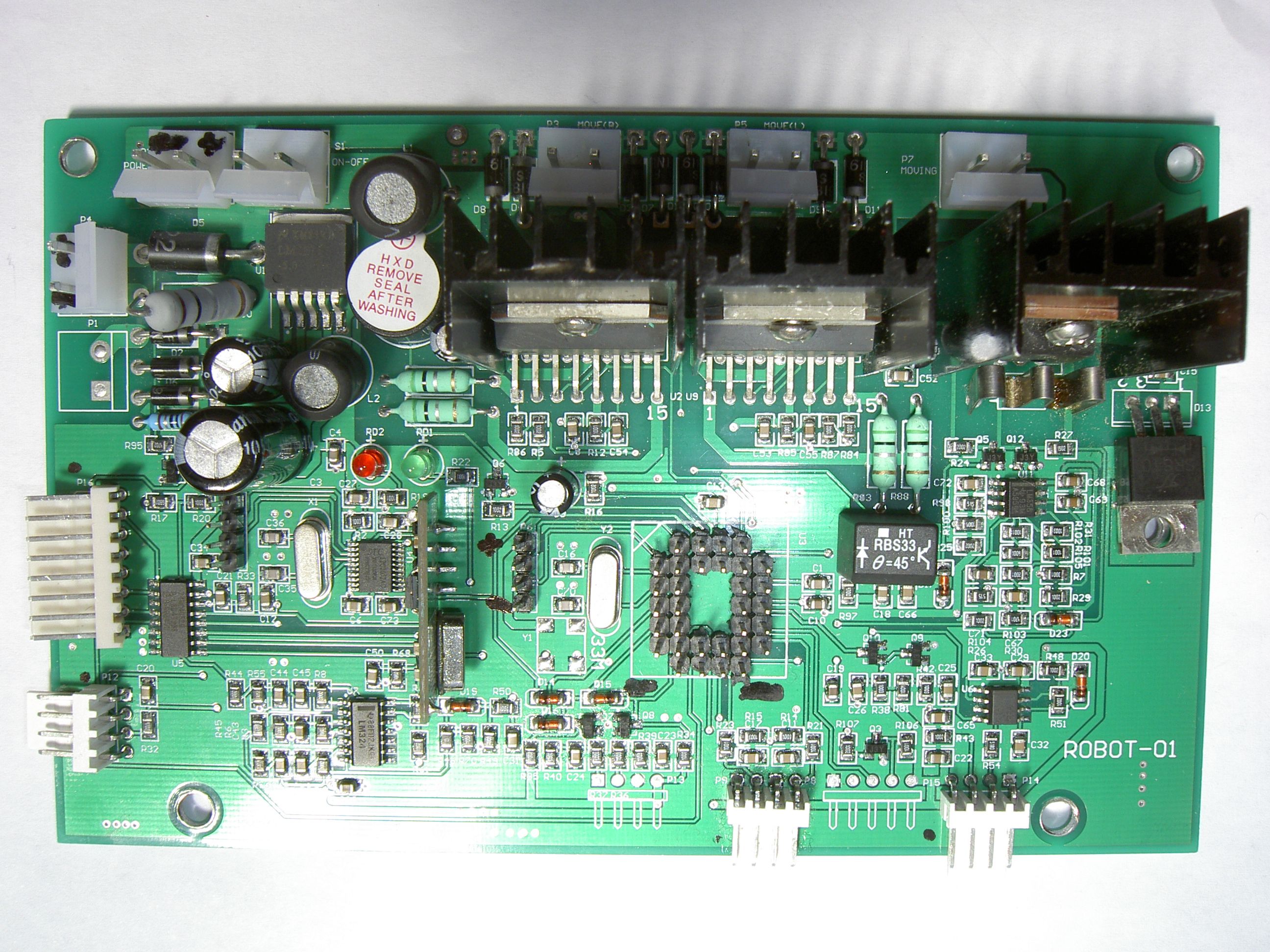
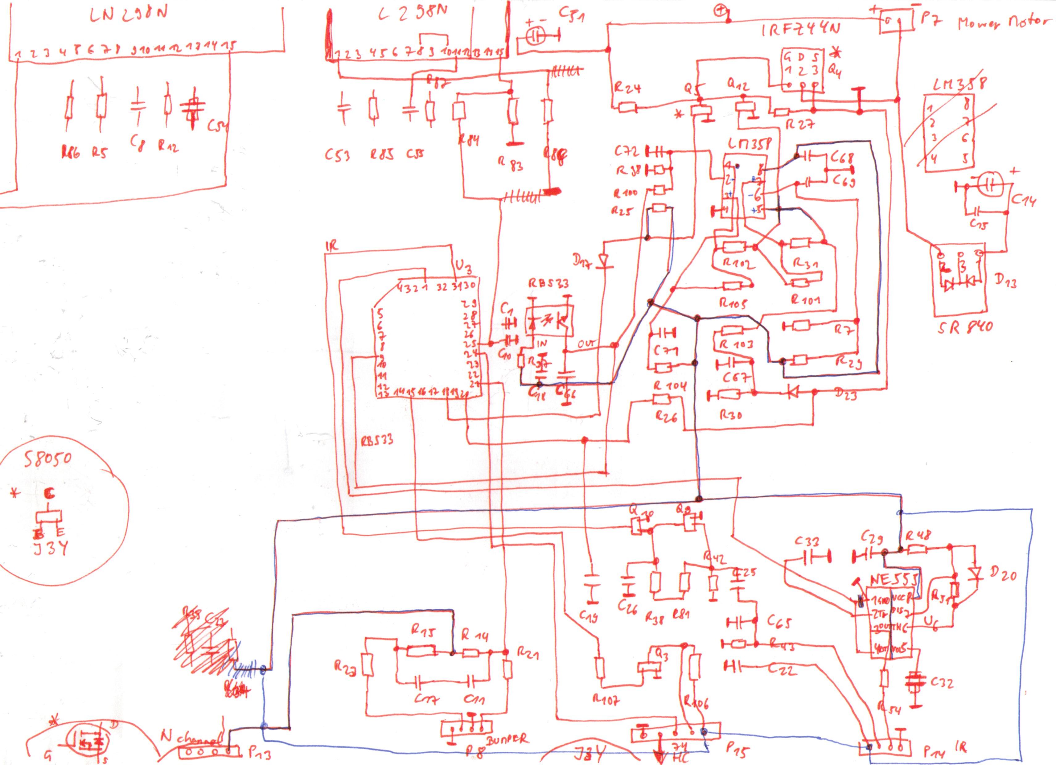
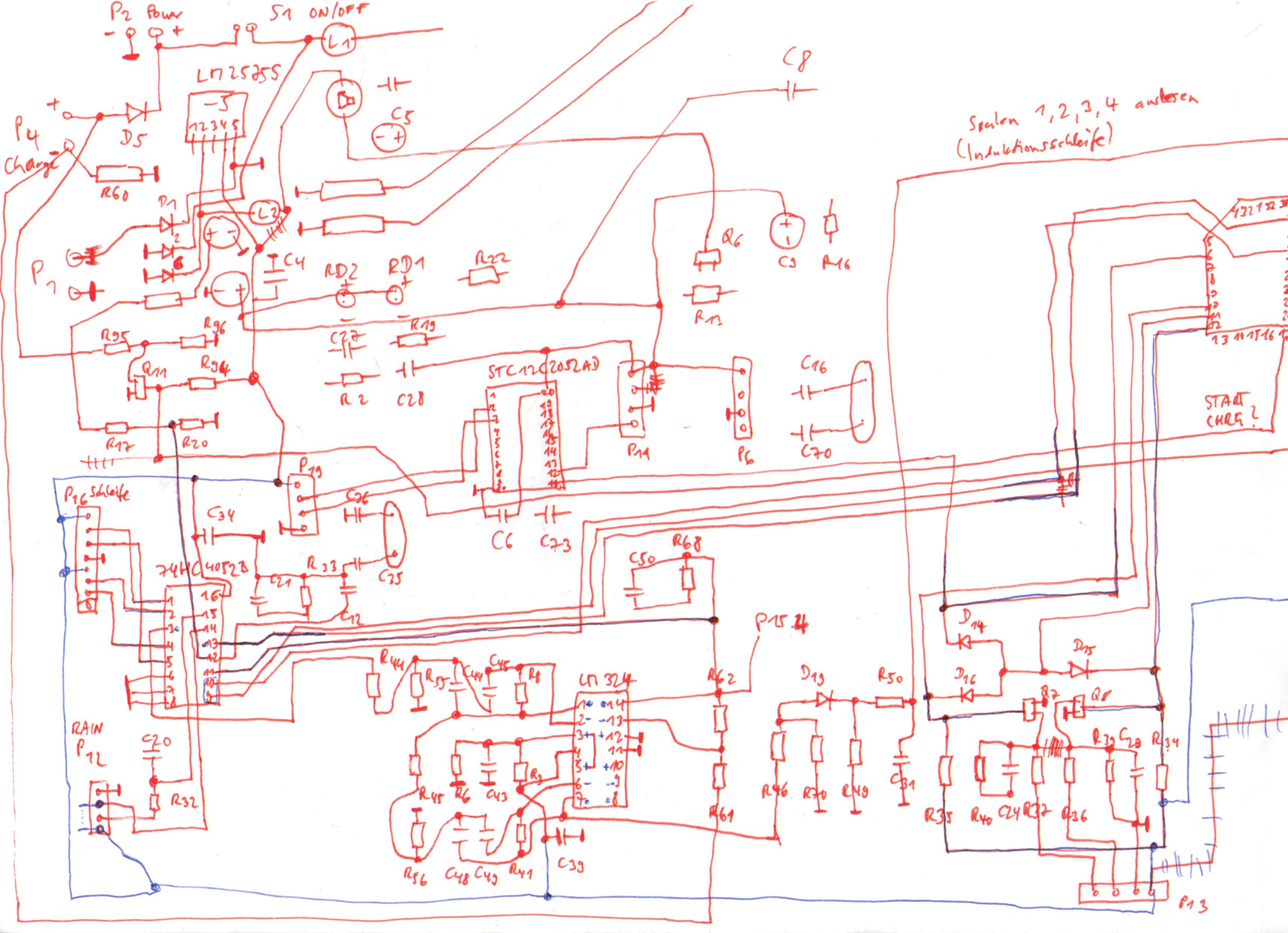
1. TC-G158 technical internals
This section should give you an overall idea of the components present in your mower. It’s good to roughly understand them for your own hacks!
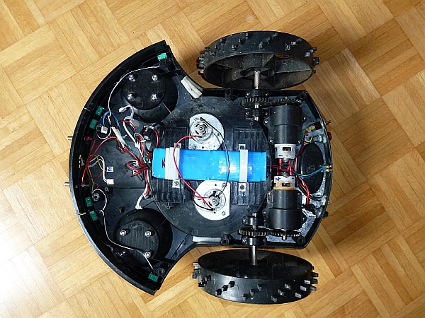
My purchased Tianchen TC-G158 robot mower has the following components:
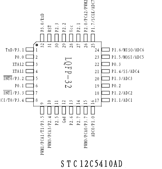
-Main MCU: STC12C5410AD (8051 clone, 10K flash memory, 33 Mhz)
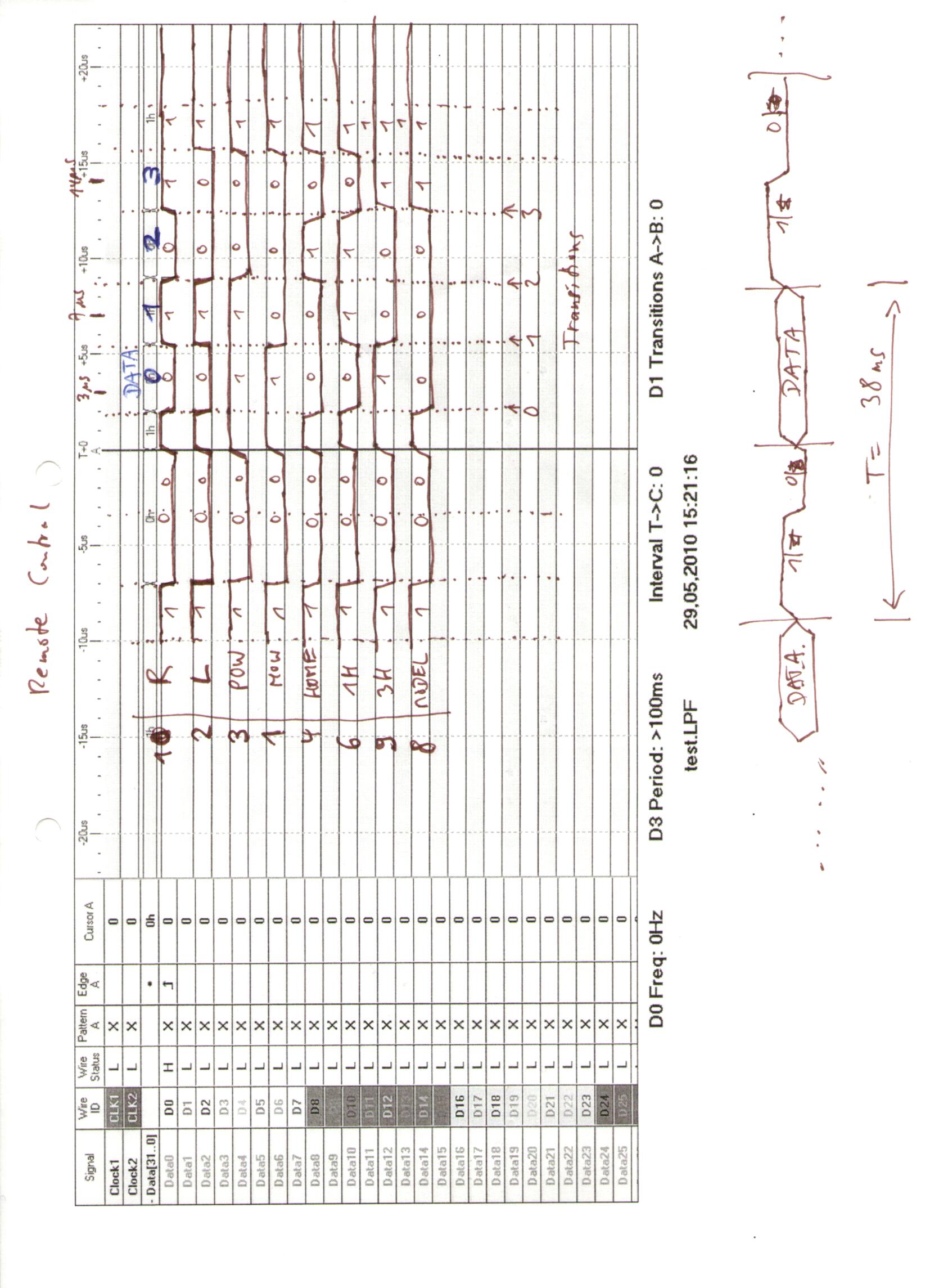
-Hope RF HM 433 Mhz receiver module (for remote control)
-Remote control decoder MCU: STC12C2052AD (sends remote control key data to main MCU, see protocol below)
-Induction unit quad op amp: LM32 (for induction loop inductor amp)
-Optical roll ball sensor: HT RBS33 (theta=45 degree , switches off mowing motor above theta degree)
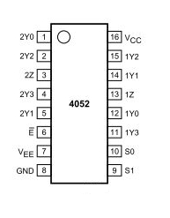
-Dual 4-channel mux/demux: 74HC4052D (to read in induction loop inductors and battery sense/rain sensor)
-Power MOSFET: IRFZ44N (for mowing motor)
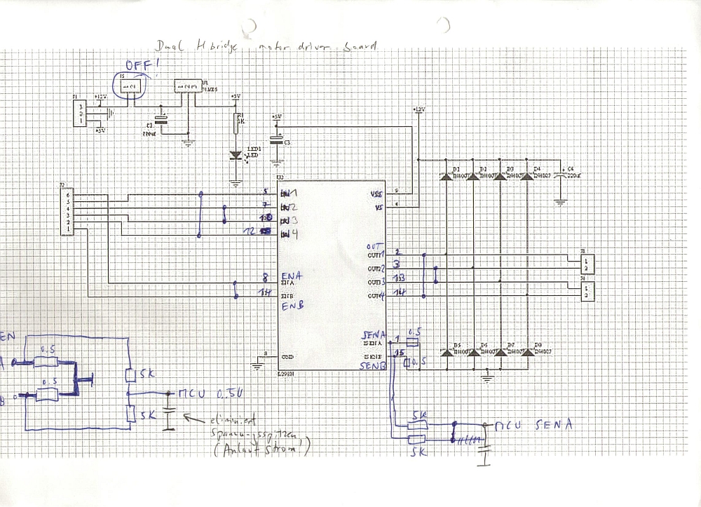
-Full bridge driver: L298N (for the left and right motors) – also see example schematics here
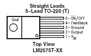
-1A step-down simple switch voltage regulator: LM2575S (for main board voltages)
-Solid state amp: SR840 (for mowing motor)
-Timer: NE555 (for IR modulation?)
-Dual op-amp: LM358 (for induction loop inductor)
–
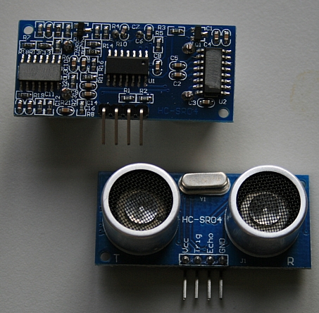
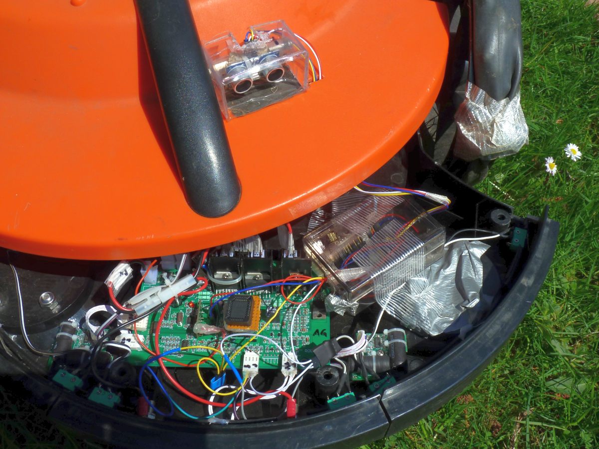
2. Adding an ultrasonic sensor (Arduino hack)
An ultrasonic distance sensor greatly helps to avoid bumping obstacles (or to drive into shrubberies). We use the HC-SR04 as it’s easy to use (you can find these boards on eBay).
This hack is universal – actually, you can add it to ANY robot mower. The good thing is you can keep the robot’s stock MCU firmware, and it’s easy to add: Just add another two wires to the front bumper push buttons, and your Arduino will simulate one of the bumpers (by switching the bumper signal to LOW) when the ultrasonic distance sensor detects an obstacle!
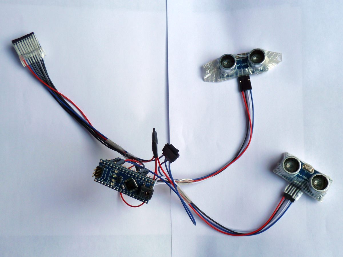
We use an Arduino Nano board for the controller as it’s very popular and very easy to program.
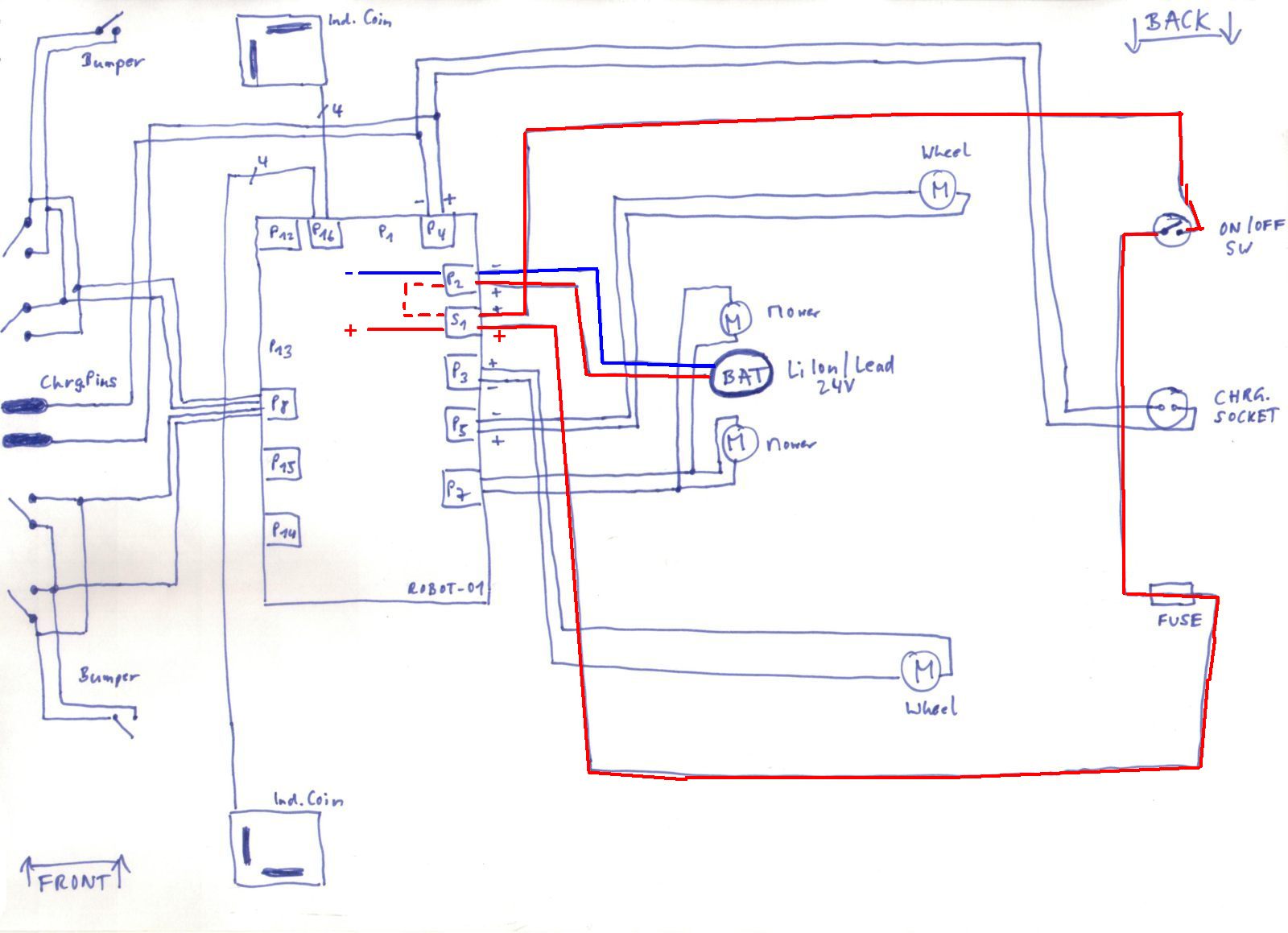
Arduino <—> robot wiring
Pin 7 <—-> robot left bumper signal pin (P8.2, see below)
Pin 8 <—-> robot right bumper signal pin (P8.4, see below)
Pin 12 <—-> ultrasonic board (trigger pin)
Pin 11 <—-> ultrasonic board (echo pin)
VCC <—-> robot +5V (P6.1, see below)
GND <—-> robot GND (P6.4, see below)
Robot bumpers pinout (P8) is (left-to-right):
1-GND
2-left bumper signal pin
3-GND
4-right bumper signal pin
Robot P6 pinout is (top-to-bottom):
1-VCC (+5V)
4-GND
(the first photo shows the version for the Ambrogio L50 robot mower using two ultrasonic sensors)
For debugging purpose, you can add a piezo speaker:
Finally, you can see everything in action (NOTE: In this video, there is no perimeter that can stop the robot, it is only the ultrasonic sensor that can stop it)
NOTE: I have not tested yet how the ultrasonic sensor can be automatically deactived when the robot drives into the charging station – I’m not using any perimeter with this robot, so at least it works without perimeter…
For Arduino code, see resources section further below.
Hardware/software used for the hack:
–
3. Replacing the stock MCU firmware (ATMEGA hack)
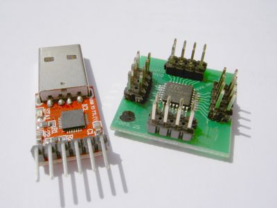
Replacing the stock MCU firmware requires to write a new firmware, and I did choose the Atmel ATMEGA-168 (on a ready myAVR board MK2 USB) as a replacement for the original 8051 MCU.
The first step is to desolder the MCU socket as you can see on my robot mower board .
Here you can see how I managed to connect my Atmel MCU to the old MCU socket (using some DIY adapter). Alternatively, you can directly connect the individual board pins to your Arduino board using 1-pin-cables (you can find them on eBay).

After a while, I noticed that I need something more fancy to upload my new custom software revisions into my mower while sitting comfortable in a chair meters away: a Bluetooth module!
The bluetooth module extends the ordinary ISP RX/TX serial line (RS232) and also allows me to monitor sensor data and robot state changes (and believe me, this feedback is absolutely necessary for debugging your code…)
So this is my final system today:
Original board <==> ATMEGA168 <==> ISP (TTL UART) <==> Bluetooth module <~~> PC (Bluetooth dongle)
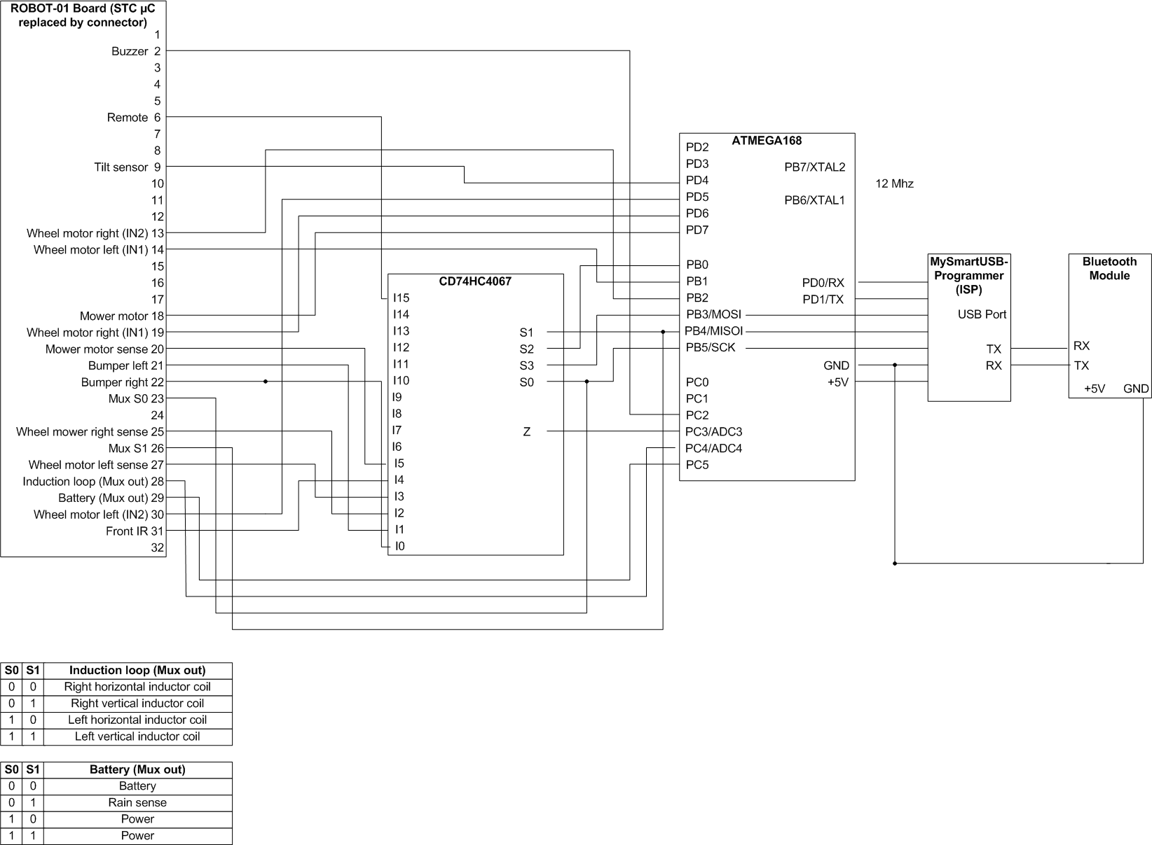
I upload new software builds into the mower via Bluetooth and the serial data of the mower is transmitted via Bluetooth too.
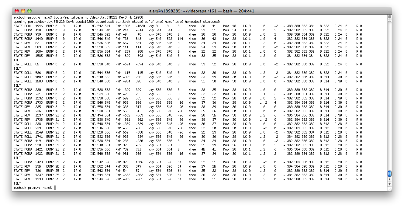
My latest software periodically displays the state of the mower (state, state time, bumper states, IR state, inclination sensor, motor PWM, motor PID controller wxy, motor current, induction coins values, battery state, rain sensor):
All components I needed for this solution:
For ATMEGA code, see resources section further below.
–
4. Adding a PID control for the wheels
After purchasing, I noticed the robot has a small problem: when moving from the lower part to the higher part of my garden, it doesn’t move a straight line – it makes circles of 90 degress and less (due to the heavy lead acid batteries my mower is using) …
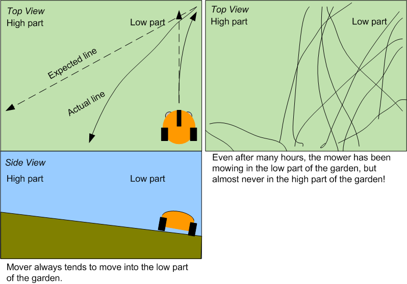
(Also have a look at my mower simulation that demonstrates the difference ‘lawn with and wihtout slope’).
So I decided to add some software PID controller to it to control the left-right wheel balance 🙂 and it solved this specific problem (see videos with and without balance controller).
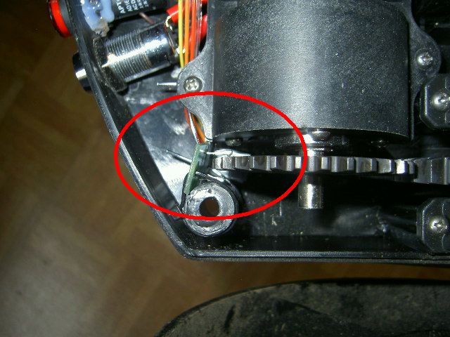
And here you can see how I added photo interruptors (LTH301-07) for the left and right motors to measure the wheel movement (for the left-right wheel balance control):
–
5. Resources (wiring diagram, code etc.)
–
6. External resources on the Internet
