Idea
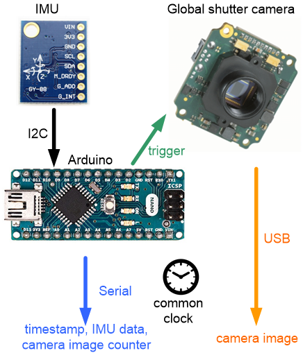
For certain applications (e.g. visual inertial odometry, SLAM, …), you may need to hardware-synchronize camera and IMU so that both use the same (millisecond precise) time base:
time:   0 ms, IMU data, camera image #0
time:   5 ms, IMU data
time:  10 ms, IMU data
...
time:  50 ms, IMU data, camera image #1
time:  55 ms, IMU data
time:  60 ms, IMU data
...
time: 100 ms, IMU data, camera image #2
...
My setup
I will describe the steps for my own setup here, however you should be able to use them for your own hardware as well.
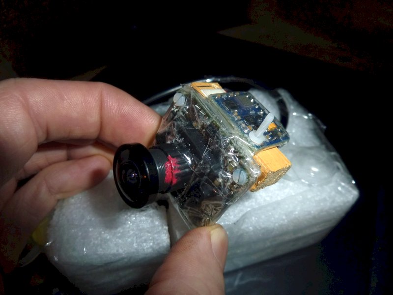
- monochrome global shutter camera (mvBlueFox-MLC200wG, ON Semiconductor MT9V034 digital image sensor) connected via USB (important: it has an external trigger pin we’ll use for hardware synchronization)
- 132 degree fisheye lense
- IMU: GY-88 (MPU6050) connected to Arduino Nano
Overview
The Arduino will calculate precise (millisecond) timestamps for each IMU measurement (200 Hz). At certain timestamps (20 Hz), it will trigger the camera (via the trigger line) to capture a new image. Timestamp and triggerCounter data will be sent to the PC (IMU node). The IMU node will receive IMU data from the Arduino and publish the time data via a new ROS TimeReference message (topic /imu/trigger_time). The camera node will subscribe to this time data to reconstruct precise time for each camera image. So, the message flow will be like this:
IMU –> Arduino –> PC (ROS IMU node) –> ROS camera node
ROS trigger_time message published by IMU node will look like this:
/imu/trigger_time  (TimeReference):

header.seq   --> image sequence (triggerCounter)
header.stamp --> timestamp of image
Arduino
- Connect camera trigger pin (digital input 0) to Arduino Pin D5 (see mvBlueFox datasheet for connector pinout).
- Install the ROS mpu6050_serial_to_imu package:
https://github.com/fsteinhardt/mpu6050_serial_to_imu - Edit src/MPU6050.ino, so that
(1) your IMU data (200 Hz) get’s timestamps and
(2) triggers the camera at certain timestamp times (20 Hz).volatile unsigned long irqTimestamp = 0; volatile unsigned long triggerCounter = 0; volatile byte irqCounter = 0; // called by MPU6050 interrupt void dmpDataReady() { irqTimestamp = millis(); irqCounter++; if (irqCounter == 10){ // trigger cam @20 Hz digitalWrite(TRIGGER_PIN, HIGH); digitalWrite(TRIGGER_PIN, LOW); triggerCounter++; irqCounter = 0; } } - Add (1) timestamp and (2) triggerCounter to the messages sent to your PC. Using the timestamp and triggerCounter, the PC can
(1) reconstruct the IMU time and
(2) reconstruct the the camera time and image number for that time
ROS: mpu6050_serial_to_imu
- Edit src/mpu6050_serial_to_imu_node.cpp, so that the new message fields (timestamp and triggerCounter) are received from the Arduino.
- Add a new publisher ‘trigger_time’ that will publish the timestamps in the IMU node so the camera node can later subscribe them:
ros::Publisher trigger_time_pub = nh.advertise<sensor_msgs::TimeReference>("trigger_time", 50); - Publish the message:
ros::Time measurement_time(ts / 1000, (ts % 1000) * 1000*1000);  // sec, nsec

ros::Time time_ref(0, 0);
trigger_time_msg.header.frame_id = frame_id;
trigger_time_msg.header.stamp = measurement_time;
trigger_time_msg.time_ref = time_ref;          trigger_time_pub.publish(trigger_time_msg);
ROS: bluefox2
- Install ROS bluefox2 package:
https://github.com/KumarRobotics/bluefox2 - Edit src/single/single_node.cpp, so that the camera node subscribes to the new trigger_time messages:
subTimeRef = pnh.subscribe("/imu/trigger_time", 1000, &bluefox2::SingleNode::callback, this); void SingleNode::callback(const sensor_msgs::TimeReference::ConstPtr &time_ref) { bluefox2::TriggerPacket_t pkt; pkt.triggerTime = time_ref->header.stamp; pkt.triggerCounter = time_ref->header.seq; fifoWrite(pkt); } - Change the ‘Aquire’ method so that the timestamps are reconstructed for each camera image:
void SingleNode::Acquire() { while (is_acquire() && ros::ok()) { bluefox2_ros_->RequestSingle(); // wait for new trigger packet to receive TriggerPacket_t pkt; while (!fifoRead(pkt)) { ros::Duration(0.001).sleep(); } // a new video frame was captured // check if we need to skip it if one trigger packet was lost if (pkt.triggerCounter == nextTriggerCounter) { bluefox2_ros_->PublishCamera(pkt.triggerTime); } else { ROS_WARN("trigger not in sync (seq expected %10u, got %10u)!", nextTriggerCounter, pkt.triggerCounter); } nextTriggerCounter++; Sleep(); } } - Change the camera launch file (launch/single_node.launch) to
(1) disable automatic exposure time and use a fixed exposure time, so you can calculate the final image timestamp based on the trigger timestamp
(2) use the trigger pin (‘trigger on HIGH’) for camera digital input 0:<arg name="aec" default="false"/> <arg name="expose_us" default="15000"/> <!-- Trigger mode (ctm): 1=on demand (default), 3=hardware trigger --> <arg name="ctm" default="3"/> <arg name="cts" default="0"/>
- Add the IMU node to the camera node launch file (launch/single_node.launch) so that the IMU node is started by the camera node :
<node pkg="mpu6050_serial_to_imu" type="mpu6050_serial_to_imu_node" name="mpu6050_serial_to_imu_node" required="true">
      <param name="port" value="/dev/ttyUSB0"/>
</node>
- Run the camera node launch file:
roslaunch bluefox2 single_node.launch - Verify that you don’t miss any time messages (see outputted ROS warning above).
Hello! Thank you very much for this great tutorial. I also would like to build up my own vi-sensor following your instructions, however, I didn’t manage to find a place to buy the global shutter camera. Could you please tell me how did you get the camera you used? I found the webpage of that company and have sent them an email asking this, but no reply yet……
Many thanks in advance!
Hi, did you check companies like http://www.watterott.com or http://www.uctronics.com – They offer breakout boards with global shutter camera chips (MT9V022 , MT9V034 , …)
Regards,
Alexander
Hello! Thank you very much for your tutorial. It’s very clear and explicit. Now, I have a similar configuration than yours and my bluefox node don’t take images. This is my response:
25002957: Error while requesting image: DEV_NO_FREE_REQUEST_AVAILABLE
25002957: Error while requesting image: DEV_NO_FREE_REQUEST_AVAILABLE
25002957: Error while requesting image: DEV_NO_FREE_REQUEST_AVAILABLE
25002957: Error while requesting image: DEV_NO_FREE_REQUEST_AVAILABLE
25002957: Error while requesting image: DEV_NO_FREE_REQUEST_AVAILABLE
[ WARN] [1546947151.816434362]: trigger not in sync (200)!
25002957: Error while requesting image: DEV_NO_FREE_REQUEST_AVAILABLE
25002957: Error while requesting image: DEV_NO_FREE_REQUEST_AVAILABLE
25002957: Error while requesting image: DEV_NO_FREE_REQUEST_AVAILABLE
My camera has changed the red light to green but there are no topic publishing. Do you know what can be my mistake? Thank you in advance.
Henríquez.
Hi, thanks for a very wonderful tutorial.
Presently I have an NVIDIA Jetson Nano to which I intend to connect the camera and IMU sensor. Jetson Nano also has a 40 pin expansion header which is further supported by the new Jetson GPIO python library.
I was wondering if instead of using Arduino to trigger the camera, I could rather use Jetson nano to accomplish the same?
What are your thoughts on this?