You can develop for STM32 using the Arduino IDE. Here are the steps:
What you need:
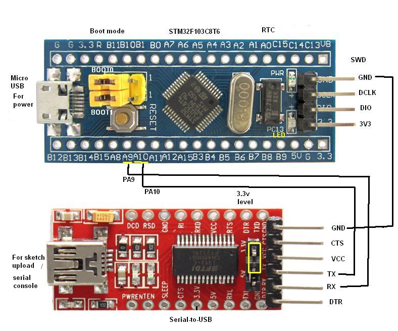
- STM32F103C8T6 module (ARM32 Cortex-M3, 72 Mhz, 64K flash, 20K SRAM, 33 I/O pins, 3.3V), you can find cheap modules on eBay
- Serial-to-USB-module (3.3V level, e.g. CH340)
Steps:
1. Wire STM32 module and Serial-to-USB module as shown below:
2. Download and install Arduino IDE (I did use 1.6.3)
3. Download ‘https://github.com/rogerclarkmelbourne/Arduino_STM32‘, extract it and copy the folder ‘Arduino_STM32-master’ to your Arduino/hardware folder (C:\Programs\Arduino\hardware).
4. Run Arduino IDE, choose settings:
‘Board: Generic STM32F103C series‘
‘Variant: STM32F103C8 (20k RAM, 64k Flash)’
‘Upload method: Serial‘
‘Port: <the COM port of your USB-to-serial adapter>’
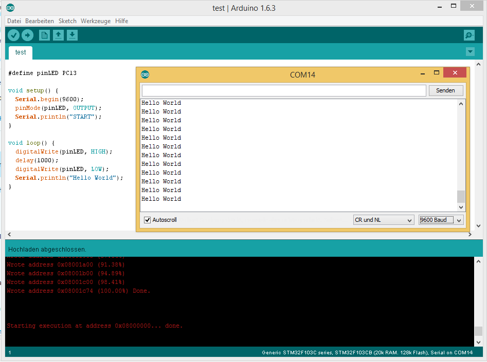
5. Compile this sketch:
#define pinLED PC13

void setup() {
  Serial.begin(9600);
  pinMode(pinLED, OUTPUT);
  Serial.println("START");
}

void loop() {
  digitalWrite(pinLED, HIGH);
  delay(1000);
  digitalWrite(pinLED, LOW);
  Serial.println("Hello World");
}
6. On the board, set ‘BOOT0‘ to 1 (will boot from system memory which contains an UART to flash uploader). Press RESET button.
7. In the Arduino IDE, choose ‘Upload‘. On the board, the blue LED will start to flash.
8. After upload completed, your sketch will start. If you want your uploaded sketch to boot automatically after next power-on/reset, set ‘BOOT0‘ back to 0 (will boot from program memory). Press RESET button.
Arduino demo code for STM32F103C8T6:
1. SPI interface
#include "SPI.h"

#define pinLED PC13
#define pinRST PB0
#define pinIRQ PB1

#define pinSPI_SS  PA4
#define pinSPI_CLK PA5
#define pinSPI_MISO PA6
#define pinSPI_MOSI PA7

volatile int irqCounter = 0;
int lastIrqCounter = 0;

void handleIRQ(){
  irqCounter++;
}

void setup(){
  pinMode(pinLED, OUTPUT);
  pinMode(pinSPI_SS, OUTPUT);
  pinMode(pinRST, OUTPUT);
  pinMode(pinIRQ, INPUT);

  Serial.begin(115200);
  Serial.println("START");
  attachInterrupt(pinIRQ, handleIRQ, RISING);

  // Initializes the SPI bus by setting SCK, MOSI, and SS to outputs, pulling SCK and MOSI low, and SS high.
  SPI.begin();

  digitalWrite(pinRST, LOW);
  delay(200);
  digitalWrite(pinRST, HIGH);
  delay(100);
}

void spiTest(){
  unsigned long msg = 0;
  SPI.beginTransaction(SPISettings(16000000L, MSBFIRST, SPI_MODE0));
  digitalWrite(pinSPI_SS, LOW);
  SPI.transfer(0x00);
  msg = SPI.transfer(0x00);
  msg = (msg << 8) + SPI.transfer(0x00);
  msg = (msg << 8) + SPI.transfer(0x00);
  msg = (msg << 8) + SPI.transfer(0x00);
  digitalWrite(pinSPI_SS, HIGH);
  SPI.endTransaction();
  Serial.println(msg, HEX);
}

void loop(){
  digitalWrite(pinLED, HIGH);
  delay(100);
  digitalWrite(pinLED, LOW);
  delay(100);
  if (irqCounter != lastIrqCounter){
    Serial.println(irqCounter);
    lastIrqCounter = irqCounter;
  }
  spiTest();
  delay(2000);
}
2. I2C interface:
#include <Wire.h>

#define OLED_address  0x3C

int pinSDA = PB4;
int pinSCL = PB5;

TwoWire MyWire(pinSCL, pinSDA);

MyWire.beginTransmission(OLED_address); //start transmission to device
MyWire.write(0x80);        // send register address
MyWire.write(0);        // send value to write
MyWire.endTransmission(); //end transmission
3.
LED blinkt nicht
void loop()
{
digitalWrite(pinLED, HIGH);
delay(1000);
digitalWrite(pinLED, LOW);
Serial.println(“Hello World”);
delay(1000); // fehlt! PC13
}
+1 on this.
#define pinLED PC13
void setup() {
Serial1.begin(115200);
pinMode(pinLED, OUTPUT);
Serial1.println(“START”);
}
Thank you for your great blog!
We look forward to seeing STM8 libraries and works also…
It would be better with example to use USB (as serial device) 🙂
USBSerial usb;
void setup() {
Serial.begin(9600);
pinMode(pinLED, OUTPUT);
Serial.println(“START”);
usb.begin();
}
void loop() {
digitalWrite(pinLED, HIGH);
delay(1000);
digitalWrite(pinLED, LOW);
delay(1000);
Serial.println(“Hello World”)
if (usb.isConnected()){
usb.write(“Hello USB”);
}
}
There’s also a bootloader:
https://medium.com/@paramaggarwal/programming-an-stm32f103-board-using-usb-port-blue-pill-953cec0dbc86
https://github.com/rogerclarkmelbourne/STM32duino-bootloader
hi
i want to using stm32f103c8 by arduino
i uploaded “generic_boot20_pc13.bin” file
i checked led(pc13) on/off
but when connect usb cable
pc didn’t link to stm32f103c8 board
i did download “install_drivers” in C:\Users\xxx\Documents\Arduino\hardware\Arduino_STM32\drivers\win
i want tip or solution
Hi Developer,
my try to program a STN32F103C8-Board with the Arduino-IDE was successful.
On the other hand to program a STM32F407-Discovery-Board produces many problem at compile-time,
although I select the necessary menu-item “Board: “STM32 Discovery F407”.
Has anyone an idea?
A step was missed in the instructions:
Run the IDE, open the Tools menu, select “Boards manager”, and install the Arduino Due from the list of available boards.
Without the Arduino Due board software installed you will get an error for a missing file when you compile.
Hi,
I though I might point out that the SPI example has a race condition.
Its not serious in the example (worse case it will not report an IRQ), but if used as a template for smth more elaborate, the race condition may bite.
The problem is here:
if (irqCounter != lastIrqCounter){
Serial.println(irqCounter);
lastIrqCounter = irqCounter;
}
If irqCounter is, say 2 and lastIrqCounter is 1, we will enter the body of the if statement.
Then an interrupt occurs and irqCounter becomes 3, so we print 3 and assign 3 to lastIrqCounter, thereby not reporting interrupt #2.
So the code that examines and changes irqCounter should be executed atomically by turning off interrupts for that section of code.
As I said above in this example the results of the race condition may only cause the developer to wonder why interrupts are being missed (not reported), but if the code was doing something more complex with the value (e.g. if irqCounter is used as an index to a buffer) it would cause chaos.
**vp