QS-909 JYQD
- low cost brushless motor driver with direction and speed control
- 12~36V, 500W (with heat sink)
- comes in two variants: 1) with motor hall sensor input and 2) sensorless
1) with motor hall sensor input (module can be purchased here)

2) without motor hall sensor input (sensorless):

The principle of the two variants of JY01: First is sensorless and second one uses motor hall sensor inputs:

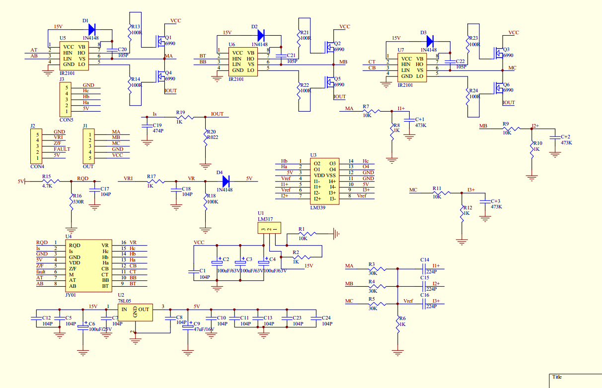
- JY01 is the brushless controller IC
- IR2101 are used for high- and low side MOSFET drivers
- NCE6690 are used for N-channel MOSFETs
- On some variants no motor hall sensors are required and the EMF detection is performed via differential comparators (LM339) by measuring the voltage drops of the ‘free’ phase in a motor step.
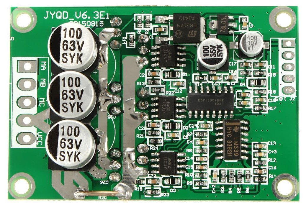
QS-909 JYQD wiring / pinout
CON4: Connect EL (motor enable) to 5v, Z/F to 5v (foward direction). Connect a 10k potentiometer for speed control (pins: 5v, VR, GND)
5v       5v output
EL       Motor enable input (5v)
Signal   speedometer output
Z/F      forward/reverse control (5v/GND)
VR       speed control (0..5v)
GND      ground
CON5: Connect your motor hall sensor outputs to Ha, Hb, Hc, connect your motor hall sensor module to 5v and GND.
5v    5v output
Ha    motor hall sensor input phase 1
Hb    motor hall sensor input phase 2
Hc    motor hall sensor input phase 3
GND   ground
NOTE: When connected, the motor hall sensor outputs (Ha, Hb, Hc) should toggle between 5v and 0v (GND) if you move the motor manually with your hands. If those signals are not completely getting down to 0v, your motor hall module already uses pull-up resistors and you may have to remove the QS-909 pull-up resistors (you can find the three resistors directly near the hall sensor connector).
OUT: Connect battery to P+, P-, connect brushless motor to MA, MB, MC.
P+   voltage input
P-   ground input
MC   motor output phase 3
MB   motor output phase 2
MA   motor output phase 1
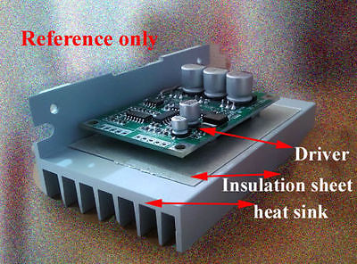
Note: if driving 60 Watts or more, use a heat sink for the MOSFETs with insulation sheet between MOSFETs and heat sink, so MOSFETs do not short-circuit.
Troubleshooting
- Motor does not start to move: Verify correct order of motor output phases (MA, MB, MC)
- Motor only moves a micro step, then stops: Verify correct order of motor hall sensor outputs (Ha, Hb, Hc). Ensure these signals toggle between 5v and 0v (GND) when moving the motor manually with your hands. If the signals are having issues getting down to 0v, remove the three pull-up resistors on brushless controller board (see notes further above)
- MOSFETs are getting hot: use a heat sink with insulation sheet between MOSFETs and heat sink (see further above)
Motor controller simulations
Online simulation of a motor controller (cascaded position and speed control)
Hallo!
Habe aus den Im Internet verfügbaren Informationen über das board und den verwendeten IC JY01 gefunden, daß alternativ zur Drehzahlansteuerung mit 0 bis 5V analog auch eine Ansteuerung mit einem digitalen PWM-Signal wie für ein RC-Servo möglich ist. Wissen Sie, wie das geht? Nur anschließen oder ist mehr erforderlich?
Mfg
Hans Gruber
we have tried this circuit and the motor runs fine while in no load. when connected to a load the motor goes off and the mosfets also get heated. we have use the mosfet IRF530 and supply to the circuit used is 15v ,5Amps.
Dear friend your video is amazing, but I have a doubt, can i connect to the controller a 10s2p 36volts 4.4ah battery of lithium-ion ? I have that doubt because when my battery is fully charge it gives 42v and the controller supports only 36v… Maybe theres a way to connect this controller and the battery when it has full charge, without burning the controller ? I need your HELP, I dont know much of electronic but i want to do an e-scooter with the parts mentioned. Please help me
i have sensorless version of this controller and i bought a heat sink, please help me, i dont want to burn the controller and i cant get another in a short time lapse
It seems that the original 36V battery will fry the board:
https://youtu.be/TaCukBg4Hj8?t=319
Dear Jesus, you should NOT connect a 36V LiPo. It will burn your BLDC driver board when it is fully charged (to 42V). The first thing that will burn is the 5V voltage regulator (an LM317). It is specified on 36V absolute maximum, and it really starts smoking above that value. Many people have already tried (including me).
By the way, the JY01 controller chip on this board seems to have more clever functions of the EL (enable) pin, according to the (Chinese) data sheet. For instance the board has a slow-start function which can apparently be modified (made faster) with the EL pin. But the data sheet is difficult to get hold of and is not complete clear to me yet. If someone knows more details, I would be interested.
Here I found a datasheet for the JY01 controller chip
http://space.cechina.cn/infosharedownload.aspx?id=1435
It’s in Chinese but Google translate helps 🙂
It states that the EL pin is multi-function foot, there are three operable states
1. JY01 application status setting at power on
2. This pin is the enable control pin when there is Hall drive. Normally high level drive, low level prohibit drive.
3. When there is no Hall drive, this pin is a starting torque adjustment pin, and the voltage range is 0.1V — 2V.
I got two boards with hall input myself.
One is working fine but the other is not working correctly. Depending on the motor start position it is showing the symptoms “Motor only moves a micro step, then stops” or it doesn’t move at all.
When I give the motor a push it is running.
Since the same motor is running fine with the first board, I assume there is no wiring issue but the second board is defective.
Can I use the version with Hall sensor input for test both type motor with and without Hall otuput?
Can I exclude the hall control?
Thank you
Mariano
SALUDOS AMIGO…
Espero me puedas ayudar … el motor que tengo es de 450w al ir aumentado gradualmente la resistencia con el potenciometro llegando cerca de los 3kΩ el motor frena… espero puedas ayudarme..
Hi great insight into the board
. A big thank you for all information. I recently purchased it and tried to run it with 12v through a smps power supply. The motor is a 1 kw motor used in electric vehicles. However i experienced intense heating of the board at 12v itself. Is there something i did wrong or is the board at fault here..
Thanks
Found an english documentation usefull, maybe someone else?:
http://m.german.brushless-dcmotor.com/photo/brushless-dcmotor/document/11756/JY01_V3.5_2018-English.pdf
Hello all,
does anyone have a datasheet for the NCE6690? I am interested in the resistance and the Miller Charge.
The JY01A is giving a speed signal, but I guess it does not give any information if the motor is rotating clockwise or counter clockwise. (Also if forward or reverse control is set, the motor could be still turning in the other direction because of an external force)
Does anyone know the operation frequency of the JY01A?
It says this is a 500 W controller, but R20 has a resistance of 22 mOhm. The JY01A limits the voltage on R20 to 0.1V, so the maximum current is 4,5A. With a supply voltage of 36V maximum, the maximum power is 163W and not 500 W. In my opinion, the use of R20 is anyway limited. If you connect a motor with low resistance and you operate with a low DC, let’s say 10%, the current on the mosfets can rise up to 10 * 4,5A = 45A before the JY01A will take any measures to reduce the current. So I would short-circuit R20 anyway and try to make a proper speed control in order to limit the maximum current.
Hi Max. I want change to 300vdc. Can you help me?
How to change it to 300VDc?
R20 need replace ?
Thank you.
Hello, how are you.
could you tell me if the hall 6851 or 3175 sensors are compatible with the controller?
Just sharing what I did looking for a high power brushless driver .
I replaced the MOSFETs with 12xP120NF10 2 in parallel on a separate heat sink board with ferrite beads and 10ohm series connection on each MOSFET gates and it handled very well where I was using to drive a 1.8KW motor on a kart for 400 lb load . Cost me an extra 20 $ though .
Bonjour ,
Svp je voudrais fabriquer un contrôleur et variateur de vitesse moteur brushless de 36v a 350W ( de Hoverboard) je les utilise dans une trotinette , j’ai besoin du schéma et mm la référence exacte des composants
Merci.
How to be when encoder needed, is it possible at all?