This page describes how to improve your delta 3d printer, so you can
- get highest effective print precision (x/y) for your prints (in my case I managed to improve from worst case 2mm print precision to average 0.1mm/worst case 0.4mm print precision )
- improve temperature control (e.g. avoid object warping)
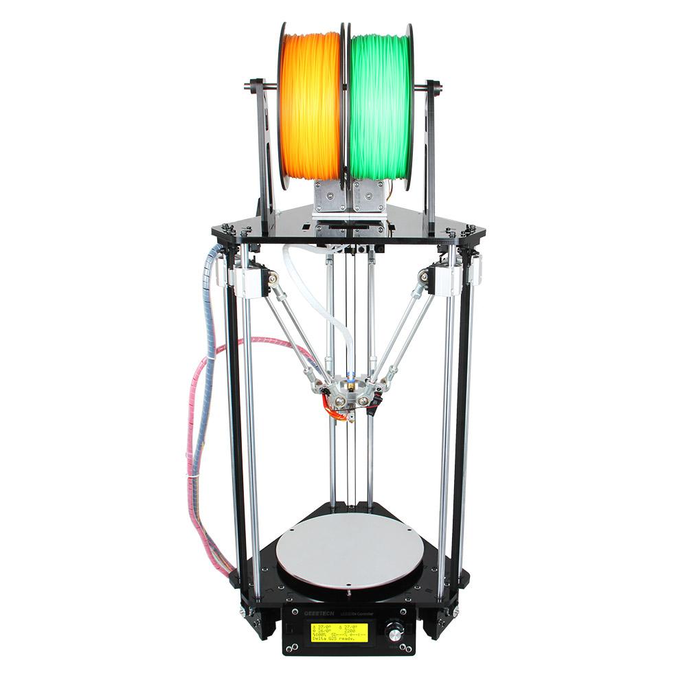
I’m using a ‘Geeetech Delta Rostock mini G2s pro‘ (170 x 200mm print volume, 0.4 mm nozzle) and Marlin firmware using the described steps below.
This articles describes how to improve your printer’s position accuracy. Additionally, you can improve overall print precision by improving your printer’s extruder accuracy.
What do I mean with print precision?
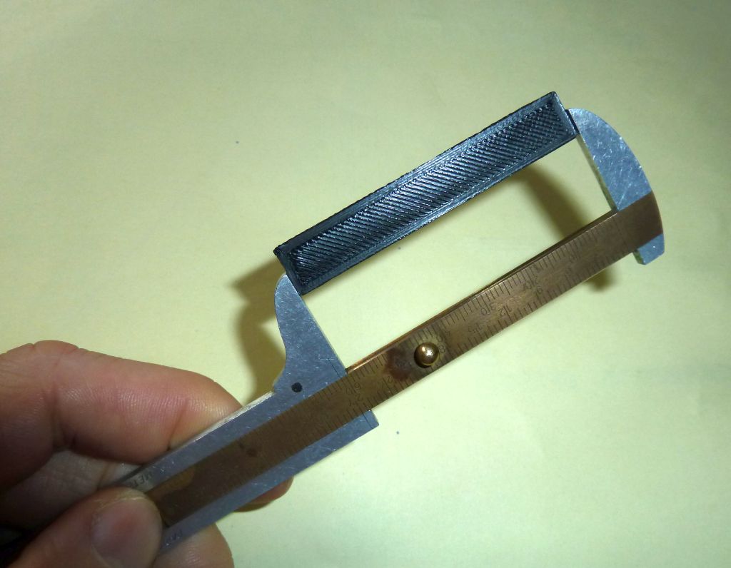
Example: let’s print a 60mm x 10mm x 2mm cube (x/y/z). You can download it here.
Now measure the cube. Does it have exactly 60mm x 10mm x 2 mm? (In my case it had 62mm x 8mm x 1.8mm, so I had 2mm precision in worst case). So let’s get better precision!
1. General calibration idea
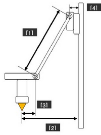
A delta printer basically consists of three triangles (at towers A, B, C). What we are trying to do is to get all triangles equal in size. Look at this picture (only showing tower A and B here):
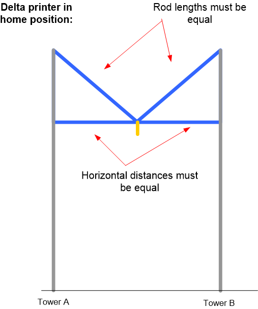
As the printer’s firmware will only know the rod length (DELTA_DIAGONAL_ROD) and the horizontal distance of one triangle (for the case when printer is in home position) (DELTA_SMOOTH_ROD_OFFSET), all of them must be equal. For a better understanding, here’s how – for a given cartesian point XYZ – the firmware computes the stepper motor position for tower A (the other towers are computed accordingly) based on Pythagoras’ theorem:
stepper_tower_a  =  sqrt( sq(DELTA_DIAGONAL_ROD)
                          - sq( -SIN_60 *  DELTA_RADIUS - cartesian_x)
                          - sq( -COS_60 *  DELTA_RADIUS - cartesian_y)
                    ) + cartesian_z
(Note: The firmware required DELTA_RADIUS will be computed indirectly by DELTA_SMOOTH_ROD_OFFSET – We will correctly get those values further below)
So let’s start calibration.
2. Verify your stepper motor tower movements are calibrated
This is a pre-check only to see if your stepper motors are controlled correctly. The firmware needs to know how many steps a delta stepper motor should move (DEFAULT_AXIS_STEPS_PER_UNIT) for one unit (mm). Let your printer go into home position. Then output the current stepper motor positions (steps) on serial console with this g-code:
M114
output is: X, Y,Z (mm-cartesian), then X, Y, Z (mm-steppers)
Now move the Z position (that’s also the tower position if you keep the XY axis in home position) down by 100mm, and output again the stepper motor positions. The stepper motor positions should have changed by the moved millimeters. If not, adjust the value DEFAULT_AXIS_STEPS_PER_UNIT in your firmware.
Note: You can calculate the theoretical value here. Example for DEFAULT_AXIS_STEPS_PER_UNIT = 80:
- 1.8° motor step angle (200 per revolution)
- driver microstepping: 1/16
- belt pitch (mm): 2
- pulley tooth count: 20
- theoretical resolution: 12.5 micron (home work: since we know the theoretical stepper resolution, what would be the theoretical overall print resolution for a delta printer?)
3. Calibrate delta rod lengths
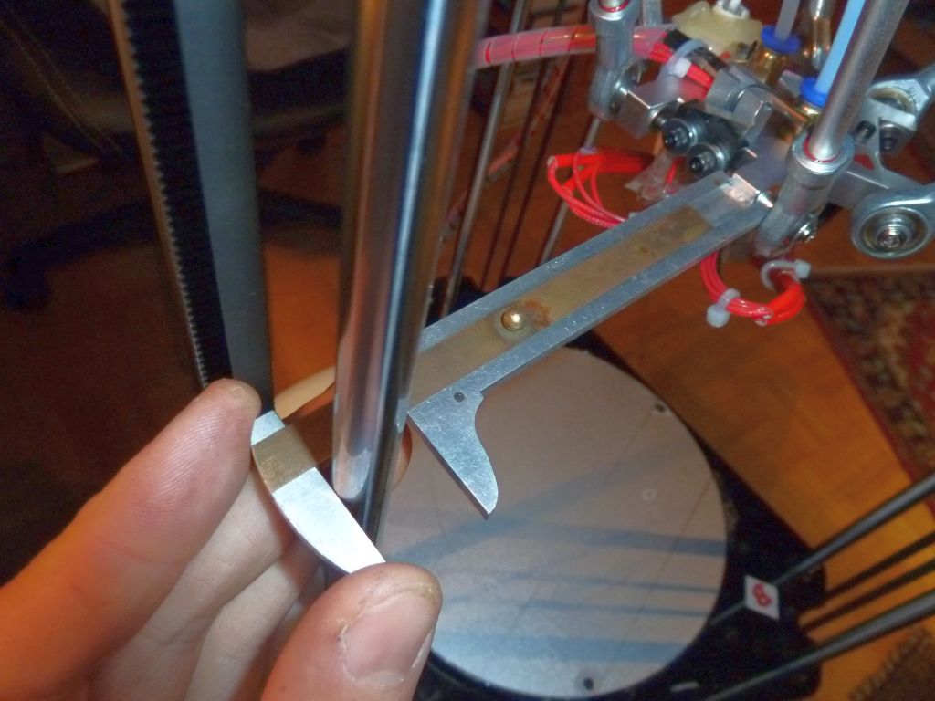
Make sure all diagonal rods (towers A, B, C) have exactly the same length [1]. If not, adjust them. Mine had a tolerance of 1-2mm before adjustment.

Set your measured rod length (mm) value in Firmware (Marlin):
#define DELTA_DIAGONAL_ROD 198
4. Calibrate delta center
Bring your machine into home position (end-position), so the print head is centered. Make sure that all rods (at tower A, B, C) have exactly the same horizontal distance to their tower when in home position [2]. Use the end-stop adjustments, so that the horizontal distances [2] are exactly all the same. After each adjustment, bring the machine into home position again and measure. I had a tolerance of 1-2mm before adjustment.
Next, we need to measure the exact distance from center point to tower [2] (when the printer is in home position) for the firmware. As it is difficult to measure the exact distance, let’s do it the other way around (try & error). Put some millimeter-paper onto your bed, add a pen to your printer head and drive 50mm into each direction (x/y) from center point.
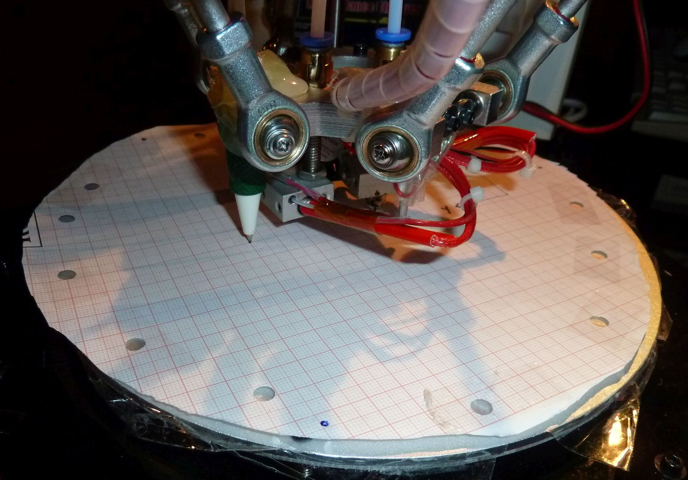
Is the moved distance correct? If not, adjust the distance (mm) in the firmware (Marlin) over and over until your head moves exactly the correct distance on your millimeter-paper:
#define DELTA_SMOOTH_ROD_OFFSET 159
5. Adjust Z axis length
Put a paper on bed, bring printer into home position once, and after that make sure that z axis zero (0) is exactly on the paper surface. Adjust the bed so that it is leveled at all positions. If required adjust z axis length (mm) in firmware:
#define MANUAL_Z_HOME_POS 203
That’s it – now print out a test object again and measure it. I had print precision 2mm before calibration (X/Y), and 0.4mm after calibration 🙂 Good luck!
6. Improve temperature control by adding an additional fan
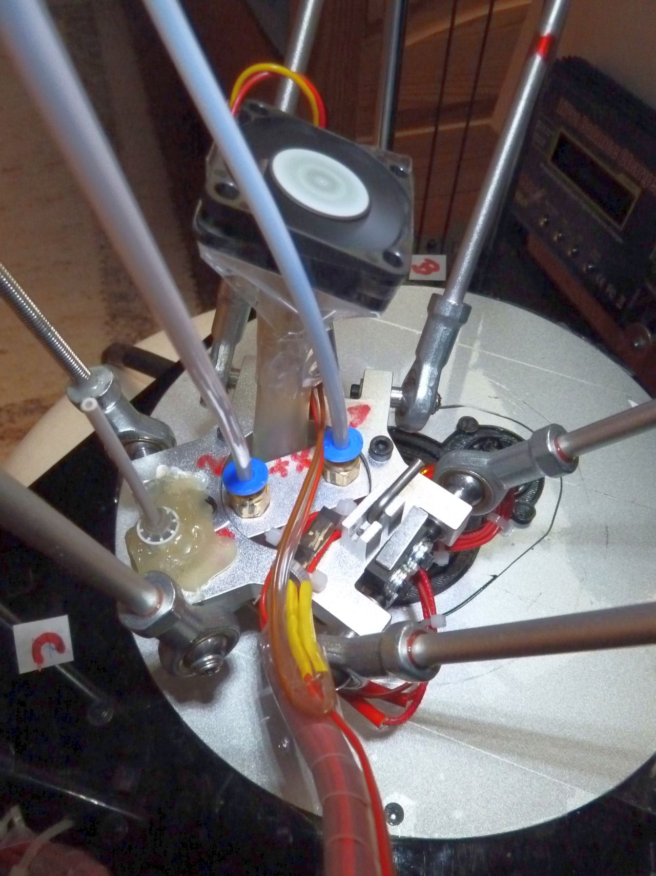
So, you object is warping while printing? Then you need an additional fan to quickly cool down the printed material. The air flow should go directly onto the printed surface (not onto the hot-end):
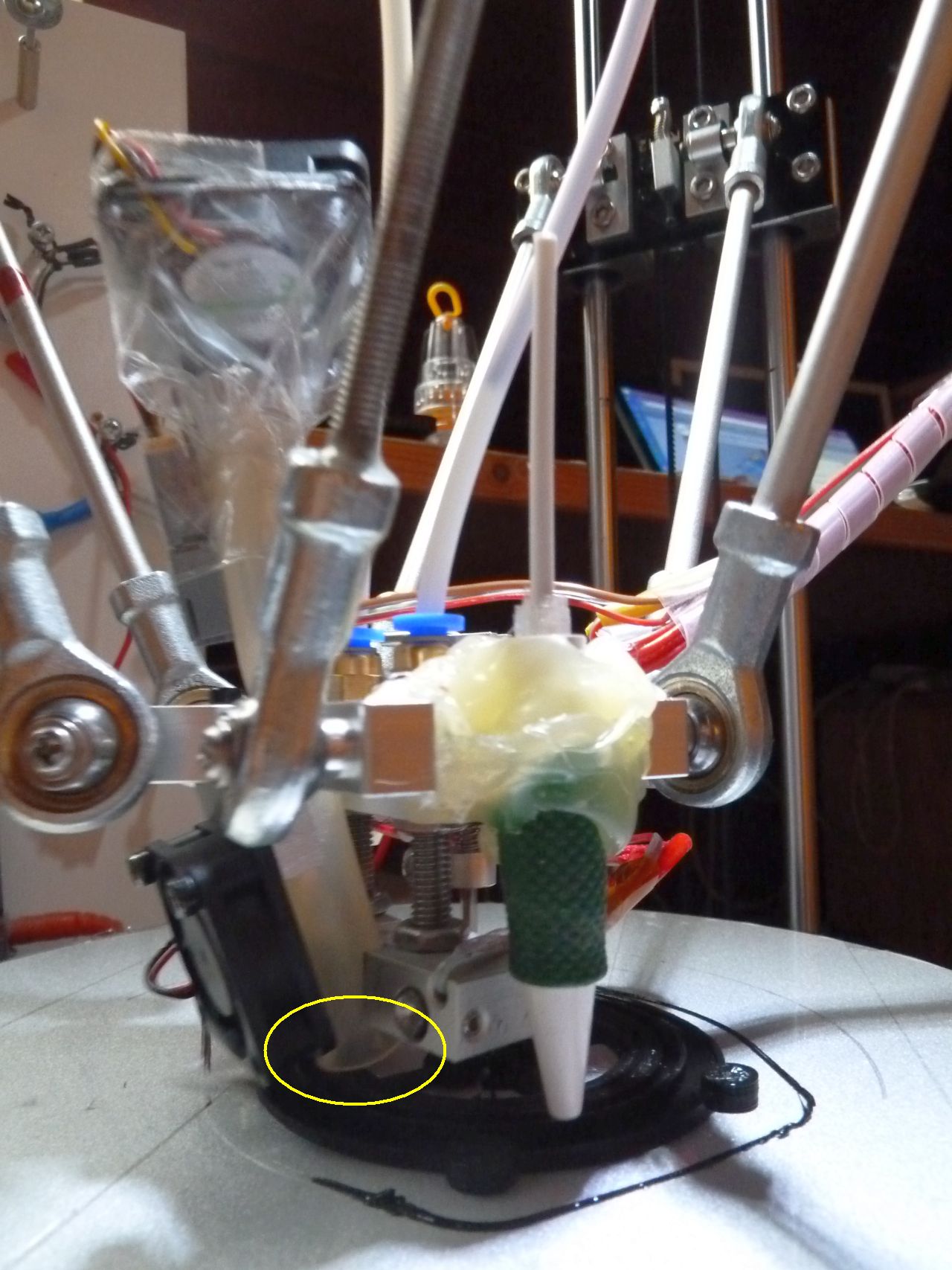
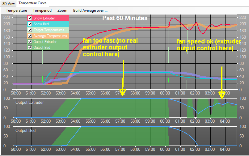
Also, make sure that your existing hot-end fan is not running too fast (so your extruder output is not over-saturated):
7. Downloads
- German quick start manual (geeetech_g2s_pro_deutsch.pdf)
- My adjusted ‘Geeetech Delta Rostock mini G2s pro Marlin firmware’
- My slic3r config file
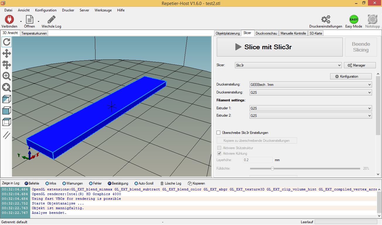
- Printer software: Repetier-Host 1.6.0 (includes Slic3r slicer software)
- Excellent CAD software: OpenSCAD
8. My Geeetech G2sPro configuration
- Printer shape: rostock, home x=0, y=0, z=max
- Printer radius: 100m
- Printer height: 204mm (adjust)
- Number extruders: 2
- Extruder 1 offset X: 0, Y: -13mm
- Extruder 2 offset X: 0, Y: 13mm
- Slicer start g-code:
G28 ; home pos
M84 S0 ; keep motors on
M106 S127 ; fan 50% speed
G4 S2 ; wait 2 seconds (otherwise you may get probe pos error)
G29 ; auto-calibration
G1 Z50 F5000 ; lift up nozzle - Slicer end g-code:
M190 S0 ; turn off bed temp
M104 S0 ; turn off extruder temp
G28 ; home
M84 ; motors off
9. Useful G-codes (Marlin firmware)
- G28 go home (always start with this) NOTE: this will forget auto-leveling!
- G29 start auto-leveling
- G28 Z100 home Z
- G1 Z50 F5000 lift nozzle
- M119 output endpoint switch states on serial console
- M114 output current xyz position (mm) AND stepper motors position (mm) on serial console (this is useful to calibrate DEFAULT_AXIS_STEPS_PER_UNIT in firmware for stepper motors)
- M106 S127 set fan PWM 50% (I have this in my start g-code)
- M84 S0 keep motors on
- M104 S0 turn off extruder temp
- M190 S0 turn off bed temp
- M84 turn motors off
- M665 set delta printer config
- G4 S10 wait 10 seconds
- M107 fan off