Hardware
For a DIY localization system using radio frequency (RF) beacons, you’ll need:
- 3x or more RF sender (beacons) that broadcast some ID periodically
- 1x RF receiver that receives ID and determines signal strength of received packet (RSSI) or time-of-flight (ToF) from all beacons, so you can finally use trilateration or a particle filter to estimate the receiver’s position
Available standards:
Ultra wideband (UWB)
- high accuracy (cm)
- measuring time-of-flight (ToF)
- IEEE802.15.4-2011 UWB (e.g. DW1000 modules: 3.5 Ghz ~ 6.5 Ghz)
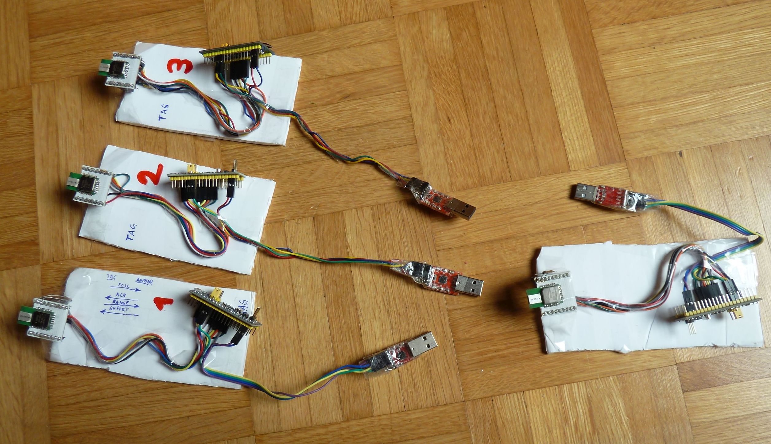
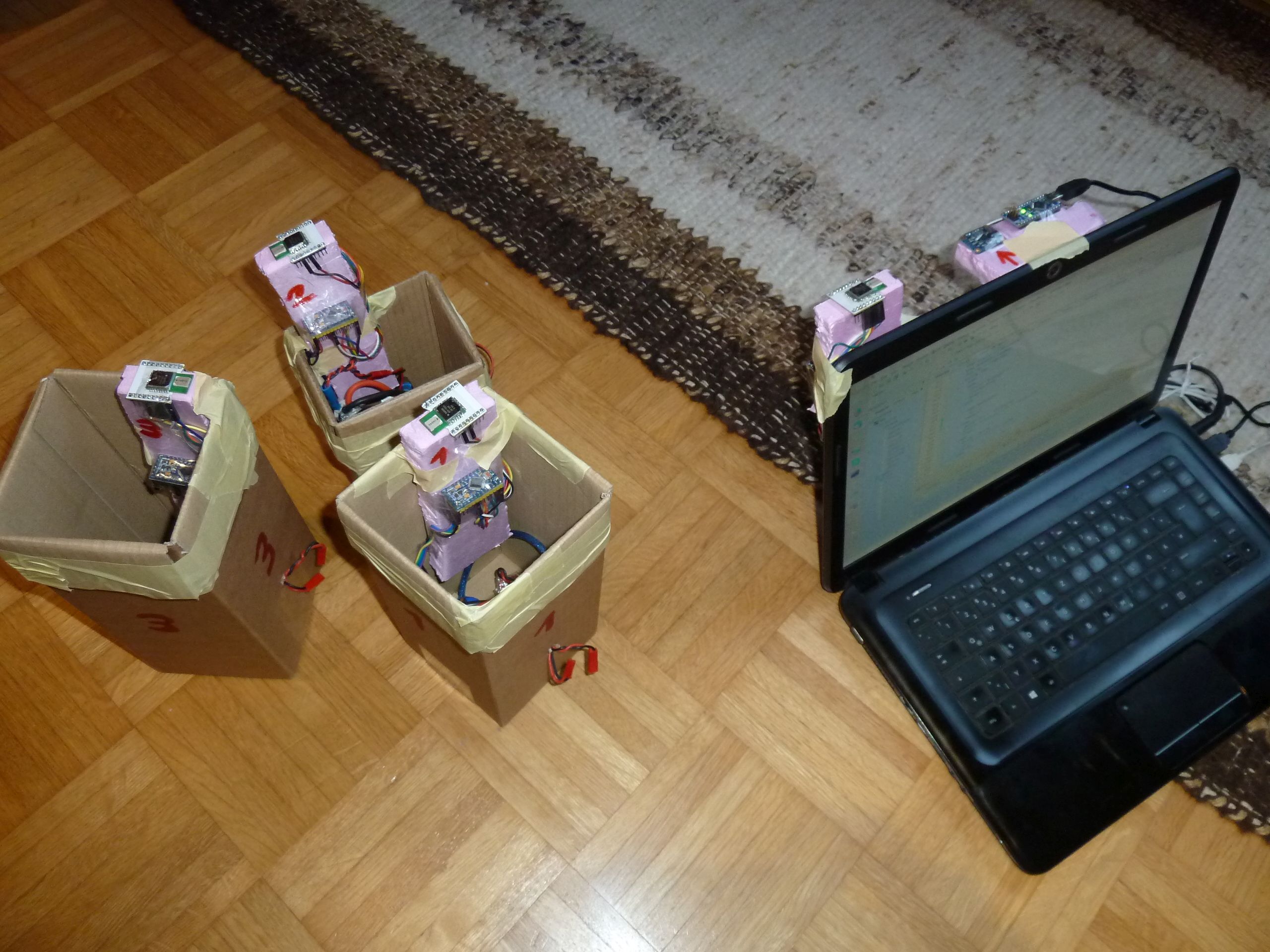
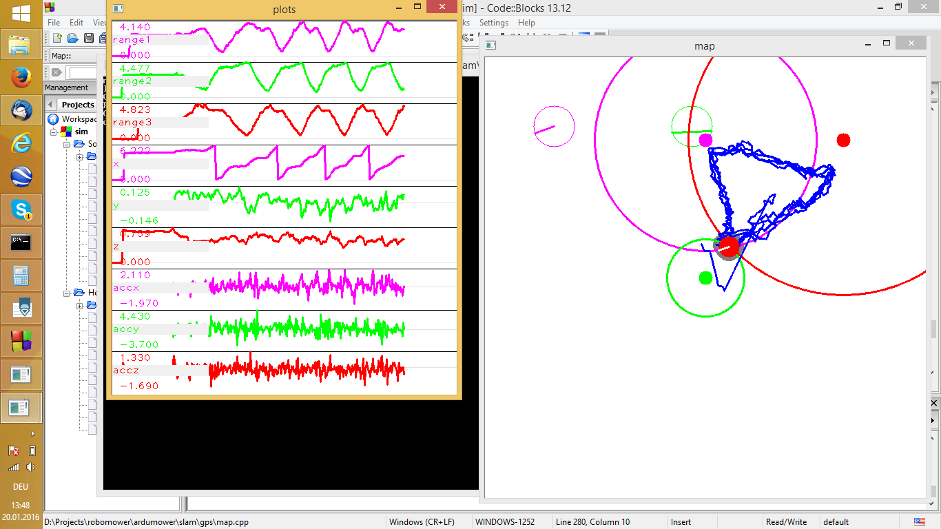
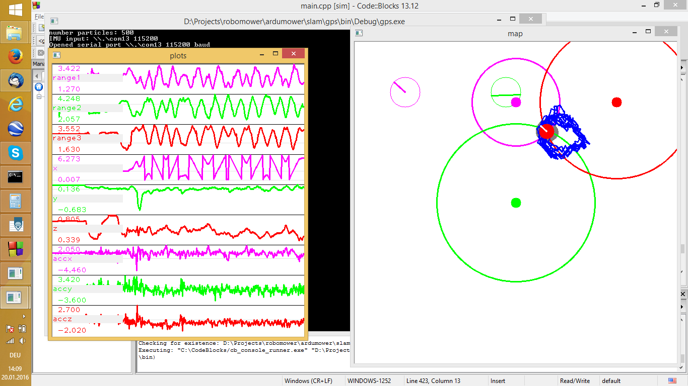
Example using 3x DW1000 ‘station’ modules and 1x DW1000 ‘rover’ module (Arduino code available):


Bluetooth BLE (4.0)
- 2.4 Ghz ISM 40 channels (2 Mhz bandwith), GFSK modulation (250 kHz deviation), uses adaptive frequency (AFH) hopping, 1Mbps data rate
- 3 channels are used by senders to broadcast (advertise) a packet every 20ms to 10 seconds:
beam packet 1: frequency 2402 Mhz, channel 37
beam packet 2: frequency 2426 Mhz, channel 38
beam packet 3: frequency 2480 Mhz, channel 39
…
beam packet 4: frequency 2402 Mhz, channel 37
beam packet 5: frequency 2426 Mhz, channel 38
beam packet 6: frequency 2480 Mhz, channel 39
… - after connected, the remaining 37 chanels are used for (optional) data connections:
frequency 2404, channel 0
…
frequency 2478, channel 36 - advertise packet structure:
- preamble (8 bit) : 10101010b = 0xAA
- access address (32 bit) : 10001110100010011011111011010110b = 0x8E89BED6
- PDU:
- size and type(16 bit)
- MAC address (6 bytes)
- fixed beacon prefix (9 bytes)
- UUID: beacon ID (16 bytes), identifies all beacons that work with the same app
- major group (2 bytes), identifies a group of beacons inside all your beacons
- minor group (2 bytes), identify uniquely one beacon
- txPower (1 byte): the 2’s complement of measured tx power at 1 meter – will be used to convert measured RSSI to meters (see software section below)
- CRC (24 bit)
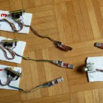
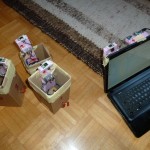
How to build sender and receiver
- Building the sender is easy (and can you find ready beam senders too)
- Building the receiver is not so easy, as you need to find a receiver chip that can tell you the RSSI of each received beam packet:
received beam packet 1 (ID, RSSI)
received beam packet 2 (ID, RSSI)
...
received beam packet n (ID, RSSI)
Possible RF chips
Can be used as beacon sender but not for receiver? (lacks the ability to tell you RSSI per received beacon packet):
- NRF51822 (MCU – GFSK)
- NRF24L01+ (Transceiver – GFSK, 1 or 2 Mhz bandwidth)
Can be used as both beacon sender and receiver (has the ability to tell you RSSI per received beacon packet):
- TICC2541 (MCU – GFSK, April Brother ABsniffer 501 UART is based on this)
- TICC2540 (MCU – GFSK, HM-10 module is based on this)
- TICC2511 (MCU – 2-FSK, GFSK, MSK – data rate seem be too small for BLE)
- TICC2500 (Transceiver – OOK, 2-FSK, GFSK, MSK, 2400-2483 Mhz – data rate seem be too small for BLE)
- …any other ?
The TICC2541 might be a good choice as it supports proprietary radio code. Flashing the CC2541 can be done via 4 wires (clock, data, reset, GND), e.g. via Arduino (CC.Flash tool).
Software
RSSI filtering
RSSI needs to be (low-pass) filtered to become accurate (try filterFactor=0.1):
filteredRSSI = beacon.RSSI * filterFactor + filteredRSSI * (1.0 - filterFactor)
RSSI to distance (meters)
Distance in meters can be calculated by txPower and measured RSSI:
double calculateDistance( int txPower, double rssi ) {
 if (rssi == 0) return -1.0; // if we cannot determine accuracy, return -1.
 double ratio = rssi*1.0/txPower;
 if (ratio < 1.0) return pow(ratio,10);
 else return  (0.89976) * pow(ratio,7.7095) + 0.111;
}
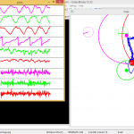
Trilateration
Trilateration estimates the receivers’s position (using 3 or more) measured distances (meters) to the beacons and the known beacons positions.
 float xa = beacon1.locationX;
 float ya = beacon1.locationY;
 float xb = beacon2.locationX;
 float yb = beacon2.locationY;
 float xc = beacon3.locationX;
 float yc = beacon3.locationY;
 float ra = beacon1.filteredDistance;
 float rb = beacon2.filteredDistance;
 float rc = beacon3.filteredDistance;
 float S = (pow(xc, 2.) - pow(xb, 2.) + pow(yc, 2.) - pow(yb, 2.) + pow(rb, 2.) - pow(rc, 2.)) / 2.0;
 float T = (pow(xa, 2.) - pow(xb, 2.) + pow(ya, 2.) - pow(yb, 2.) + pow(rb, 2.) - pow(ra, 2.)) / 2.0;
 float y = ((T * (xb - xc)) - (S * (xb - xa))) / (((ya - yb) * (xb - xc)) - ((yc - yb) * (xb - xa)));
 float x = ((y * (ya - yb)) - T) / (xb - xa);
 // now x, y  is the estimated receiver position
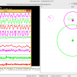
Particle filter
An alternative to estimate the receivers’s position is to use a particle filter instead of trilateration.
Interesting particle filter online demos:
- Particle filter demo
- http://www.claudeonthe.net/ai/particle_filter/particle_filter.html
- http://soswow.github.io/Various-JS-and-Python/JS/ParticleFilter/
- http://www.taylorchasewhite.com/projects/localization/
…to be continued
Hey there, I’m doing a project that requires a system like the ones you described, in wondering just about the range, do you have any data on the range of the systems you described? I’m currently thinking about IR because I can get diodes that go up to 35m.
Thank you for sharing information.