GDB/FreePascal – How a debugger can trigger on variable corruption

Problem: Some variable is overwritten in your program and you need to find the location where this will happen.

Example: As you can see from the program output, the variable ‘otherdata’ has been corrupted by the variable ‘data. Imagine, between the corruption and using again the variable ‘otherdata’ million of code lines could be executed!

program project1;
type p64 = ^int64;

procedure testme;
var
  otherdata: integer;
  data: integer;
begin
  writeln('data=',hexStr(data, 8));
  writeln('otherdata=',hexStr(otherdata, 8));
  writeln;

  p64(@data)^:=$00AABBBBCCCCDDDD;  // overwrites otherdata
  writeln('dummy');
  writeln('dummy');
  writeln('data=',hexStr(data, 8));
  writeln('otherdata=',hexStr(otherdata, 8));
end;

begin
  testme();
end.

C:Projectsfrtestdebugger>project1.exe

data=7FFDB000
otherdata=0042C294
dummy
dummy
data=CCCCDDDD
otherdata=00AABBBB


Solution:
GDB has the ability to ‘watch‘ for variable changes and trigger them! In this example, it will stop execution at the line that corrupts the OTHERDATA variable.

C:\Projects\fr\test\debugger>gdb project1.exe

GNU gdb 6.8
Copyright (C) 2008 Free Software Foundation, Inc.
License GPLv3+: GNU GPL version 3 or later <http://gnu.org/licenses/gpl.html>
This is free software: you are free to change and redistribute it.
There is NO WARRANTY, to the extent permitted by law.  Type “show copying”
and “show warranty” for details.
This GDB was configured as “i686-pc-mingw32″…
(gdb)

(gdb) break TESTME
Breakpoint 1 at 0x4014ff: file project1.lpr, line 23.

Breakpoint 1, TESTME () at project1.lpr:23
23        writeln(‘data=’,hexStr(data, 8));

(gdb) watch OTHERDATA
Hardware watchpoint 2: OTHERDATA

(gdb) continue
Continuing.
data=7FFDC000
otherdata=0042C294

Hardware watchpoint 2: OTHERDATA

Old value = 4375188
New value = 11189179
TESTME () at project1.lpr:27
27        writeln(‘dummy’);

Hopefully this feature will get into Lazarus soon 😉
8051 Quickstart using STC MCU

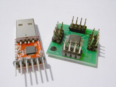
This article describes the first steps how you start programming a 8051 compatible MCU (aka C51), in this case the STC12C5412AD using a USB-to-TTL adaptor.

stc_usb.jpg

Why 8051/C51 ?

  • very popular (you can find plenty of code examples)
  • simple to program (simple register maps etc.)
  • cheap
  • Todays 8051 compatible MCUs have most needed integrated (flash memory, EEPROM, ADC, UART, PWM, …)
  • almost nothing has changed since its beginning (same registers – the 1980’s code you find still works)


Why STC MCU?

  • cheap
  • easy to flash: no external programmer is required – TX/RX line is used to flash the MCU

What you need:

  • STC MCU (STC12C5410AD, STC12C5412AD, STC12C5620AD, …) – here we using the LQFP-32 pins version (right chip in the picture above)
  • USB-to-TTL (5V) adaptor like in the picture above (these can be found easily via eBay) – my adaptor uses the popular CP2102 USB-to-UART bridge
  • Wire, adaptor board, …
  • a PC
  • a book about 8051 programming (STC doesn’t provide a real 8051 programming reference paper, however this isn’t needed as their MCUs are 100% compatible to the original 8051 generic MCU programming !)

Steps:

  1. Connect the STC MCU to the USB-to-TTL adaptor:
    USB-adaptor TX <—> MCU RX
    USB-adaptor RX <—> MCU TX
    USB-adaptor +5V <—>  MCU VCC
    USB-adaptor GND <—> MCU GND
    That’s too easy isn’t it? 🙂
  2. Download STC ISP software v4.80 (Chinese user interface) – I needed v4.80 for my MCU, newer MCUs need newer ISP versions!
  3. Download Keil uVision IDE and Compiler (evaluation)
  4. Install uVision, create a new project “Atmel AT89S52”, no startup file. Under Project options, set OSC frequency, and check “hex file” output.
  5. In uVision, create a new file (test1.c), and add it to the project.  Write your first MCU program in this file.
  6. Add the corresponding STC MCU header file to your project and include it (e.g. STC12C5410AD.H or STC12C5620AD.H). They contain the port and memory definitions for your type of MCU. You can find them in the download below.
  7. Compile to .hex file
  8. Upload .hex file using the ISP software.  Important: the STC MCU automatically starts reading and flashing the program via RX line when a certain sequence is sent at start up – therefore, you first need to start the ‘Download’ in the ISP software, and _after_ that turn on the MCU !  Also, both the ISP software and MCU will automatically handshake a good baud rate  (e.g. if the internal 6 Mhz OSC is used, the ISP software will probe a ‘good’ baud rate, so that the MCU will start downloading).

Downloads:

stc_demo.zip
(shows how to initialize the UART, ADC and successively sends the value of ADC0 via UART to the PC)