This article gives an introduction for the GPS keywords DGPS, multi-band and RTK and shows performance demos of some specific RTK GPS systems.
Why DGPS?
The earth ionosphere leads to reflections of the satellite signal, and that changes (increases) the time-of-flight (ToF) of the signal leading to error-prone distances (wrong measurements) at the GPS receiver.
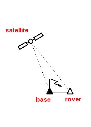
The solution to this problem is relative measurement (differential GPS): measuring time-of-flight at a 1st near-by static GPS receiver (the ‘base‘) and then using the time difference of the 2nd GPS receiver (the ‘rover‘) measured time-of-flight to compute the relative distance to the static base (see above triangle). DGPS will bring you into the 1cm precision-level (Note: precision at the alone is often not enough, you may also need robustness – more on this further below).
So for a robust RTK GPS system one typically need:
- 2x RTK capable, multi-frequency GPS receivers (one for ‘base’ and one for ‘rover’) with good GPS antennas
- 2x radios to send the correction signal continuously from base to rover (a correction signal every few seconds is sufficient)
Where should the base station be located?
The base GPS system should be located not more than several kilometers away from the rover and it should be located on a fixed point with good sky view so it receives the best signal.
Why multi-frequency?
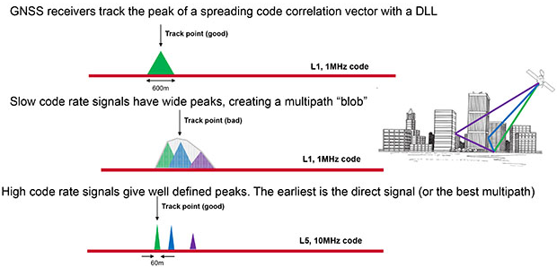
Using multiple GPS frequencies (L1,L2,L5 etc.) allows to filter out a signal that did not come directly from a satellite but instead was reflected at a building etc (multi-path). The higher the frequency the more defined the peaks, and the easier to filter out the unwanted multi-path signals. A multi-frequency GPS receiver will make your GPS robust.
Why RTK?
A RTK GPS system will do the computation of the precise GPS position based on the correction signal automatically (integrated into the receiver) and in realtime.
RTK tries to calculate the exact number of radio wavelengths between the satellites and the base station antenna (aka ambiguity resolution) and yields to either a fixed or a float solution. In a fixed solution, the number of wavelengths is a whole number, or integer, and the algorithm is constrained to yield a whole number (a fixed solution typically generates precise coordinates down to 1 cm). In a float solution, the the ambiguity is allowed to be a decimal or floating point number. If the sky view is reduced, the number of satellites is reduced and a float solution is only possible. A float solution typically generates precise coordinates up to approx. 45cm.
Available ‘low-cost’ RTK GPS systems
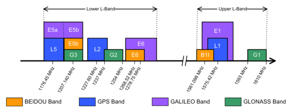
This table shows some low-cost RTK GPS receivers (up to approx. 500 EUR) and the supported satellite frequencies (L1, L2, L5 etc). Generally speaking, the more frequencies supported, the more robust the system is against multi-path.
Summary of available multi-band RTK GPS systems

                  GPS L1 L2 L5      GLONASS G1 G2    BDS B1 B2 B3     Galileo E1 E2 E5a E5b
------------------------------------------------------------------------------------------
reach rs+ (ublox m8p) x                     x            x                    x
piksi multi           x  x                  x  x         x  x                 x  x
ublox f9              x  x                  x  x         x  x                 x          x
quectel lg69t         x     x                            x  x                 x       x
allystar hd9311       x  x  x               x  x         x  x  x              x  x    x  x
unicorecomm ub4b0     x  x  x               x  x         x  x  x              x       x  x
skytraq px1122r       x  x                  x  x         x  x                 x          x
Antennas
Depending on the used frequencies of the GPS receiver (L1, L2, L5 etc.) the antennas have to support all the required frequencies too. Additionally, a good antenna also helps to filter out multi-path signals (example: a signal coming from the ground cannot be a direct signal).
Some selected antennas:
- Swift Navigation Mini survey antenna GPS500 (L1/L2, G1/G2, B1/B2/B3, SBAS) … 195,- USD
- Tallysman TW3870 / TW3872 (L1/L2, G1/G2, B1/B2/B3, SBAS) … 260,- EUR
- Tallysman TW3865 / TW3867 (L1/L2, G1/G2, B1, E1) … 180,- EUR
- ANTCOM OmniSTART/CRPA
- Maxtena M1227HCT-A2-SMA (L1/L2, G1/G2)
- ABRACON AEAGMK148060-S1575 (L1/L2/L5, B1/B2/B3, G1/G2) … 140,- EUR
- taoglas GPDF.47.8.A.02 (L/L2, G1) … 18,- EUR
- taoglas GPSF.36.7.A.30 (L1/L2) … 14,- EUR
Use case: Piksi Multi performance demos
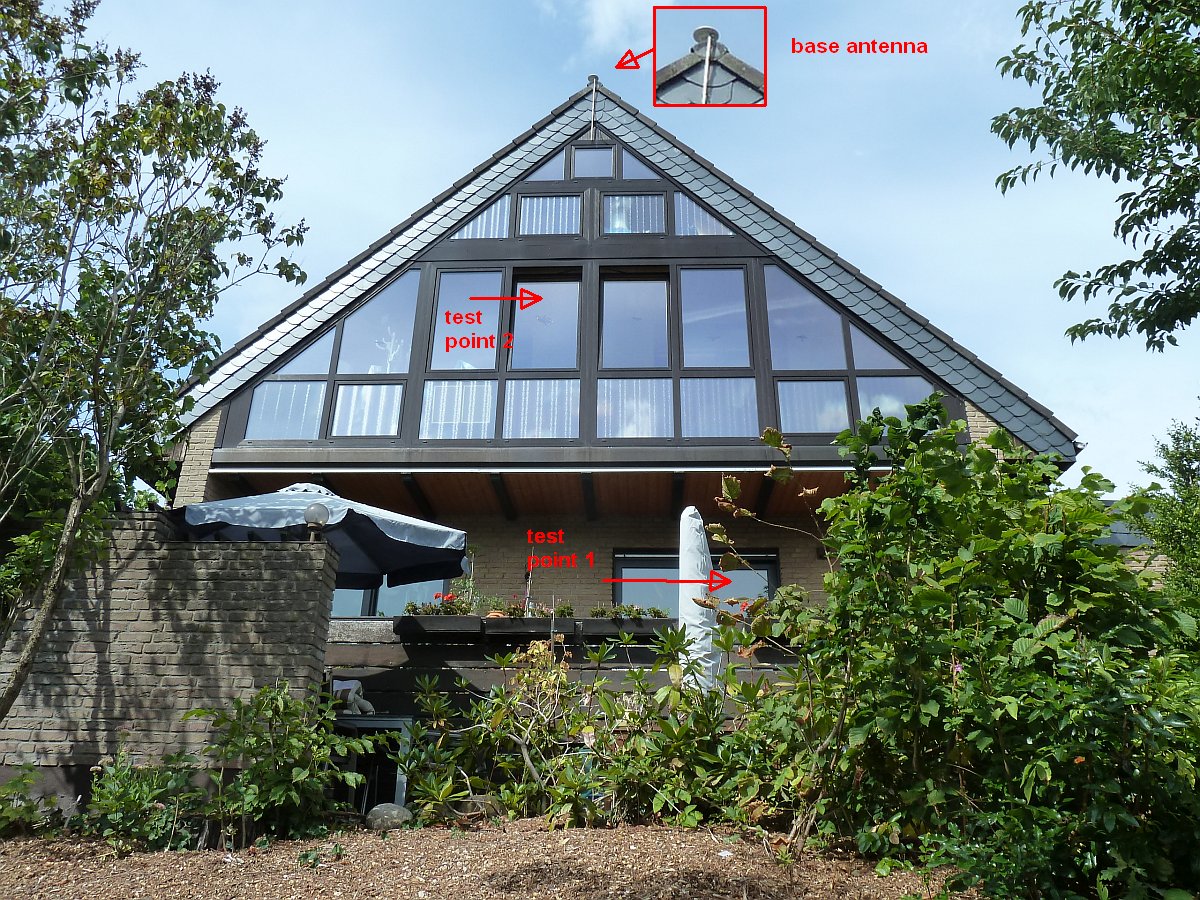
- Swift Navigation Piksi Multi (Firmware v2.0) directly near a building (see test points 1, 2 in photo above)
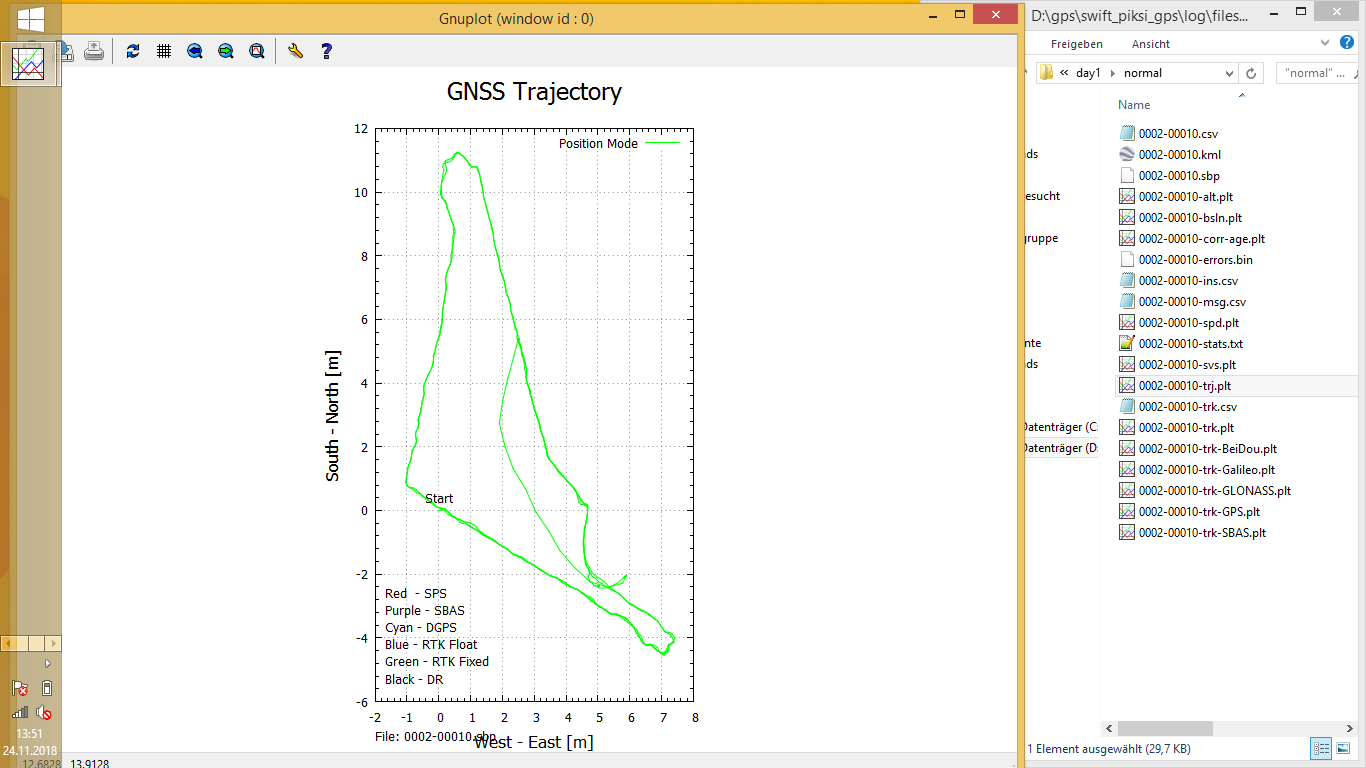
https://www.youtube.com/watch?v=pX8zVqCzg4g - Swift Navigation Piksi Multi (Firmware v1.4.5) in the backyard
https://www.youtube.com/watch?v=Cg5fSGUQWnM
Logging a test track
You can enable logging in the Piksi Multi via Swift Console. Using ‘sbp2report’, Gnuplot plots can be generated for the log files and using ‘Gnuplot’ these plots can then be visualized.
test track1: robot mower tracking a challenging track (around a hut, many nearby obstacles, trees etc.) several times by a guidance wire and logging GPS data – max. position error is less than 40cm.
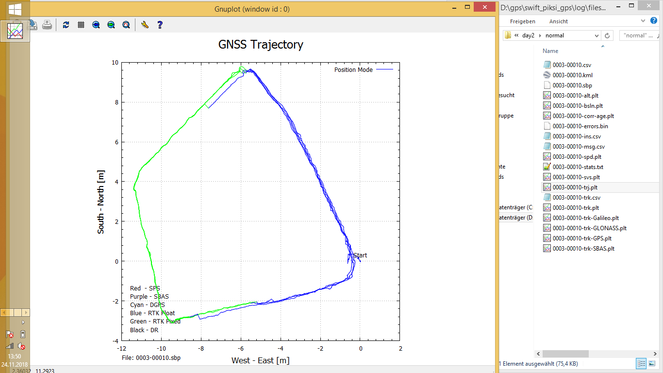
test track2: robot mower tracking an easy track (not so challenging, few obstacles only) several times by a guidance wire and logging GPS data – max. position error is less than 1cm.
RTK GPS demo applications
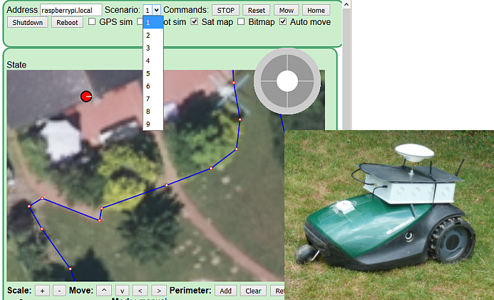
1) Robotic lawn mower
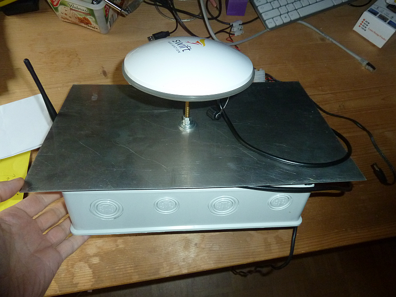
DIY box with Piksi Multi GPS receiver evaluation board and 2.4 Ghz radio

(Click here for more information)
Mr. Grau,
I am thinking to reproduce your test for this DGPS with minimum cost and apply the localization to the robot mower. I still think probably this is the better way than others such as you tested: LiDAR, Radio frequecy beacons, outdoor slam etc.
Is the antenna on your roof “a simple patch antenna” in your pictures?
I am located in the US, will the same RAW output capable GPS receivers (I am thinking to get the SkyTraq NS-HP too) ?
What would be your most preferable way to remove the Perimeter Wire? DGPS, LiDAR, Radio Frequency beacons or outdoor slam by RGB-D cameras?
Thanks
Jack
Hello Jack,
DGPS: Yes, I’m using simple patch antennas. I have tested it on the ground (with trees, buildings etc.), and unfortuneately, I cannot get a fix (solution) on the ground. The problem is reflections from trees and buildings. A single frequency GPS will probably only work without any trees, building etc. in the surroundings.
Perimeter: I think it’s still the way to go. 2D Lidar doesn’t work reliable in 3D (3D Lidar is too expensive), Radio beacons only work again without any obstacles (I have tested Decawave DW1000 outdoor). RGB-D may work (outdoor maybe for some cm distance), but requires a lot of cpu power.
In the project ‘http://www.ardumower‘ we are using perimeter and can now localize the robot’s position on the ground (using odometry, compass, gyro and a particle filter).
Regards,
Alexander
Hello Mr. Grau,
Thanks for you quick reply and insights. Also thanks for the arduemower team to bring such a good project to everybody. I think the technologies are there (some need more research) however we need to find a cost effective way to apply them on house-hold level robots. Are you or any members of the ardumower team planning to do any further research and test on GPS (multi-frequecy?), 3D LiDAR & RDB-D with a more powerful CPU in future? I think these are still very interesting directions for future R&D efforts.
I was trying to find the topic on the website about “using perimeter and can now localize the robot’s position on the ground (using odometry, compass, gyro and a particle filter).” Could you advise the link about it?
Thanks
Jack
Hello Jack,
I’m helping with software development on the Ardumower. And yes we are looking into all directions, but research takes time and money. We cannot finance this all ourselves.
A working prototype of the idea (‘using perimeter and localize on it and in it’) is currently only in German and can be found here:
http://www.ardumower.de/index.php/de/forum/software/827-ardumower-software-sunray
Regards,
Alexander
I would be up for doing some trials using differential GPS. I have about 3 robotic mowers and find a perimeter wire too limiting. [ Lack of flexibility of placement of children’s play equipment] and difficultly reaching remote field via narrow track, that has no power or services.
I’m looking at using the reach modules which may be accurate to 5cm in open skies.
https://emlid.com/reach/
I live in a windmill and will be able to place the basestation on the roof. Will be interesting to find out how accurate things are if the rover is close to the house. I suspect I will need a mix of sensors to fully do away with the perimeter wire.
Initially I would like to get a basic inaccurate (3m) gps solution working and try in a largish field. Is there any basic code available for this purpose on Arduino, so I don’t start reinventing the wheel. Rather build on the Ardumower project and feedback. Anyone thinking of doing something similar, please get in touch – more fun working together!
Many thanks
Clive
Hi Clive,
I’m starting a project that’s similar to an Ardumower. I also decided to get started with the u-blox NEO-6M, to see how accurate I could get with the least expensive GPS option.
But I think that the u-blox NEO-M8P Base and Rover configuration like the Reach is where I need to be to get real cm level accurate. But the Reach or Drotek Tiny RTK are not cheap and I would like to have a number of rover units. The NEO-7P seems to offer a level of accuracy greater than 2.5m (~<1m) with SBAS + PPP at slower speeds and measurement durations, but also supports DGPS.
These chip sets have not been out very long, but it seems like there should be more products that offer the RTK abilities the NEO-M8P has to offer. I might wait to see what else comes out for drone aircraft applications before trying to create my owe. I wish there was a NEO-M8P unit with a LoRa RFM69HCW chip, instead of bluetooth or Wifi.
Robi
Could you comment on how two (or more) GPS RAW receivers could be utilized on a platform (no external base station) are used to compute absolute platform orientation without the need for magnetic compass, etc.? I’m aware that commercial solutions exist for this (so called “satellite compass” or “GPS compass”), but I’d be interested in looking at low-cost DYI implementations, if that’s feasible.
The idea is to measure the time difference of the received signal between two (2D case) or three (3D case) antennas:
http://www.cactusnav.com/images/satcomp.jpg
(Source: http://www.cactusnav.com/newsdesk_info.php?newsPath=17&newsdesk_id=16)
The RAW receivers send phase, signal data, and clock – so in principle it’s possible assuming that you get the clock’s synchronized (either in hardware or in software). I have not seen any DIY attempt though. Even if you get it working with DIY hardware, it will only work without signal reflections, so you will need a good sky view without any obstacles in the near and far range at the height of the antennas.
What is your intended usage, why not using a magnetic compass? 🙂
The intended usage is accurately measuring winds from the combination of aircraft heading and airspeed and GPS ground velocity. The story I hear from those who do this for a living is that mag compasses aren’t precise enough. I have seen implementations of a dual GPS system that gets the aircraft orientation more accurately and reliably from the phase difference of the arriving GPS signal. But I don’t know exactly how it’s done and whether it could be implemented with off-the-shelf components without buying a commercial (expensive) satellite compass.
Hi Mr Grau:
Thanks for the interesting tutorial. I wanted to know where I can obtain Skytraq (Navspark) GPS modules in Europe.
Thank you,
Alireza
In case anybody is interested we just launched the simpleRTK2B, the first low cost multiband RTK evaluation board for the ZED-F9P GNSS module, compatible with Arduino and Pixhawk autopilots.
If you want to see all the details you can go here: https://kck.st/2NhLhBW
That’s great news! Thanks for the info 🙂
Where can I buy a board equipped with the Allystar HD9311 chip?