Fast alle Rasenmähroboter verwenden eine Induktionsschleife (also einen geschlossenen Leiter von Punkt A nach Punkt B), um den Roboter auf das zu mähende Gebiet zu begrenzen – wie findet man aber die Stelle heraus, falls so eine Leitung einmal unterbrochen wurde? Ganz einfach: man baut sich einen “Cable Tracker” 🙂 …
Funktionsprinzip: Speist man eine Wechselspannung gegen Erde (als Masse) auf den unterbrochenen Leiter, so erzeugt diese ein elektrisches Feld um den Leiter. Dieses Feld kann man mit einer Spule detektieren. Wählt man für das Wechselsignal eine Frequenz von z.B. 400 bis 4000 Hz, so kann man dieses Signal um den Leiter herum mit einem kleinen Verstärker (z.B. Walkman) hörbar machen.
Verwendete Komponenten:
Der Sender:
Eine fertige PWM-Motor-Controller Schaltung (min. 30V), gefunden bei eBay (ist quasi ein fertiger Rechtecksignal-Frequenzgenerator mit Verstärker)
Ein Gleichstromnetzteil (30V – Achtung: auf keinen Fall mit höherer Spannung arbeiten)
Der Empfänger:
Eine Spule mit vielen Windungen aus einem alten 230V-Relais
Ein alter Walkman (oder Mikrofonverstärker)
Schritt 1: Den Senderaufbauen
Zunächst wurde der PWM-Controller mit nur 10Volt und einem Lautsprecher als “Motor” betrieben, und dabei die fertige PWM-Schaltung durch einen parallel ergänzten Kondensator so eingstellt, dass die Schaltung ein Rechteck-Signal mit gut hörbarer Frequenz erzeugt. Danach wurde der Lautsprecher entfernt, das Netzteil angeschlossen und als “Last” das offene Ende der Induktionsschleife und die “Rückführung” über einen Erdungsleiter (einfach ein Stahlrohr in die Erde gerammt).
Schritt 2: Der Empfänger
Ein alter Walkman wurde geöffnet und anstelle des Tonkopfes eine Spule angeschlosen. Wenn man nun den Walkman betreibt, hört man in der Nähe von Netzteilen/Steckdosen/etc. das typische 50 Hz Brummen – ein Zeichen dafür, dass der Empfänger funktioniert.
Schritt 3: Das Induktionskabel “abfahren”
Zum ersten Test nimmt man das Kabel für den Erdungsleiter einfach in die Hand (damit ist der abzufahrende Induktionskabel geerdet). Nun hört man in der Nähe (1-2 m) des Induktionskabels einen Ton, dessen Lautstärke durch Annäherung an das Kabel zunimmt. Genau an der Stelle der Unterbrechung hört der Ton auf und man hat die Stelle der Unterbrechung gefunden.
In the year 2009, I did purchase a Tianchen TC-G158 robot mower (via ChinaVasion) and this article describes some of the robot’s electronics internals, how to add an ultrasonic sensor to it, and how to connect your own microcontroller (e.g. Arduino) to the robot mower board so that you can write your own custom software for it. One primary warning already: Everything that includes opening your robot will loose your robot’s warranty. If you really need to do this (like me), be aware of this.
If you are talent enough, my material should give you a good start for your own experiments and adjustments – Happy mowing 🙂
–
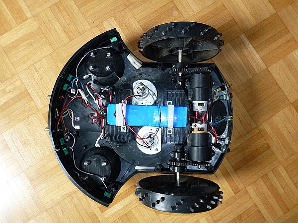
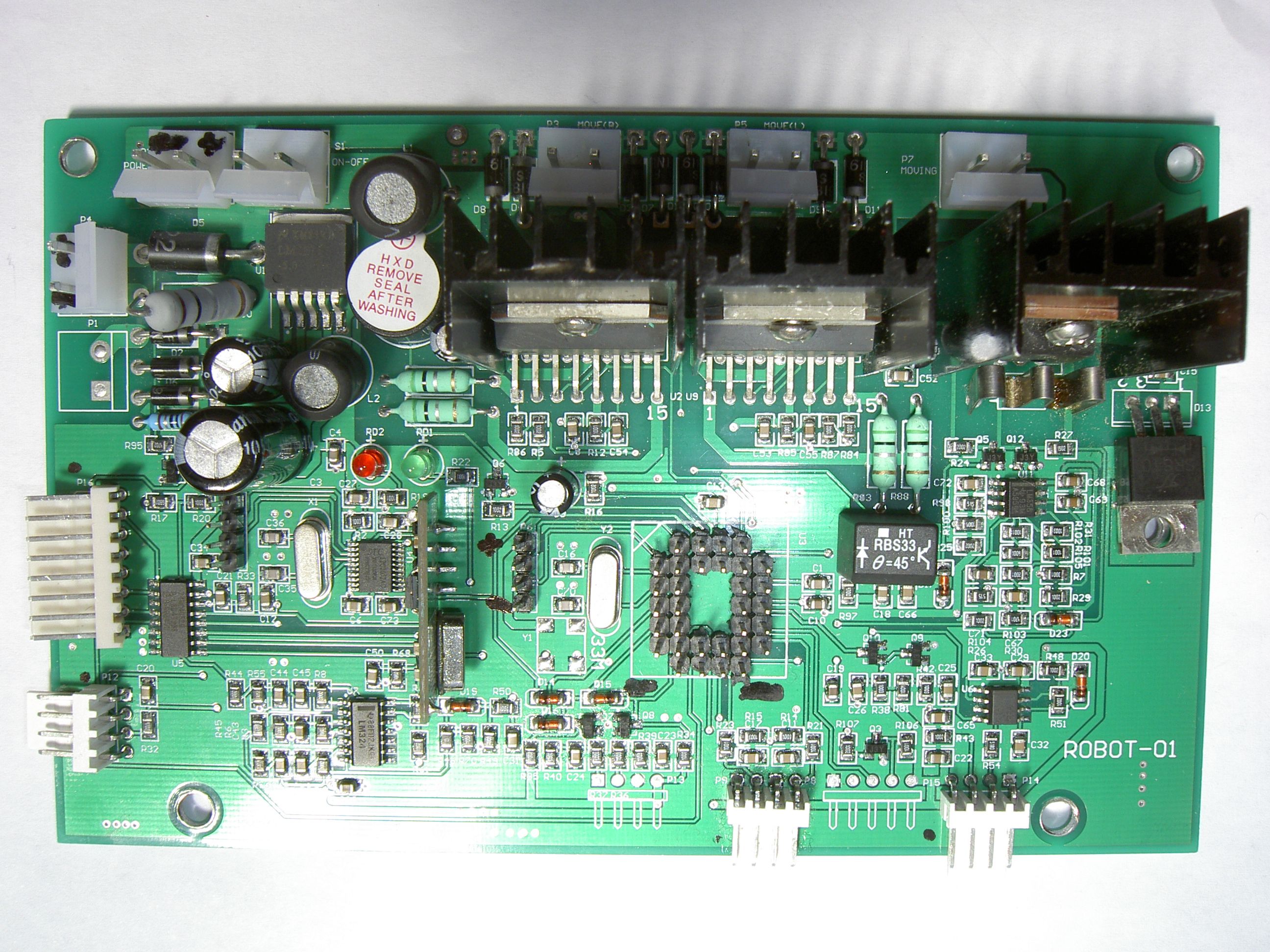
1. TC-G158 technical internals
This section should give you an overall idea of the components present in your mower. It’s good to roughly understand them for your own hacks!
My purchased Tianchen TC-G158 robot mower has the following components:
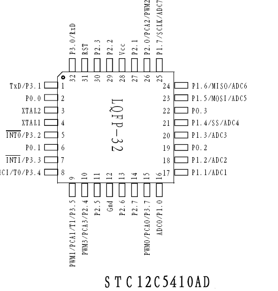
-Main MCU: STC12C5410AD (8051 clone, 10K flash memory, 33 Mhz)
-Hope RF HM 433 Mhz receiver module (for remote control)
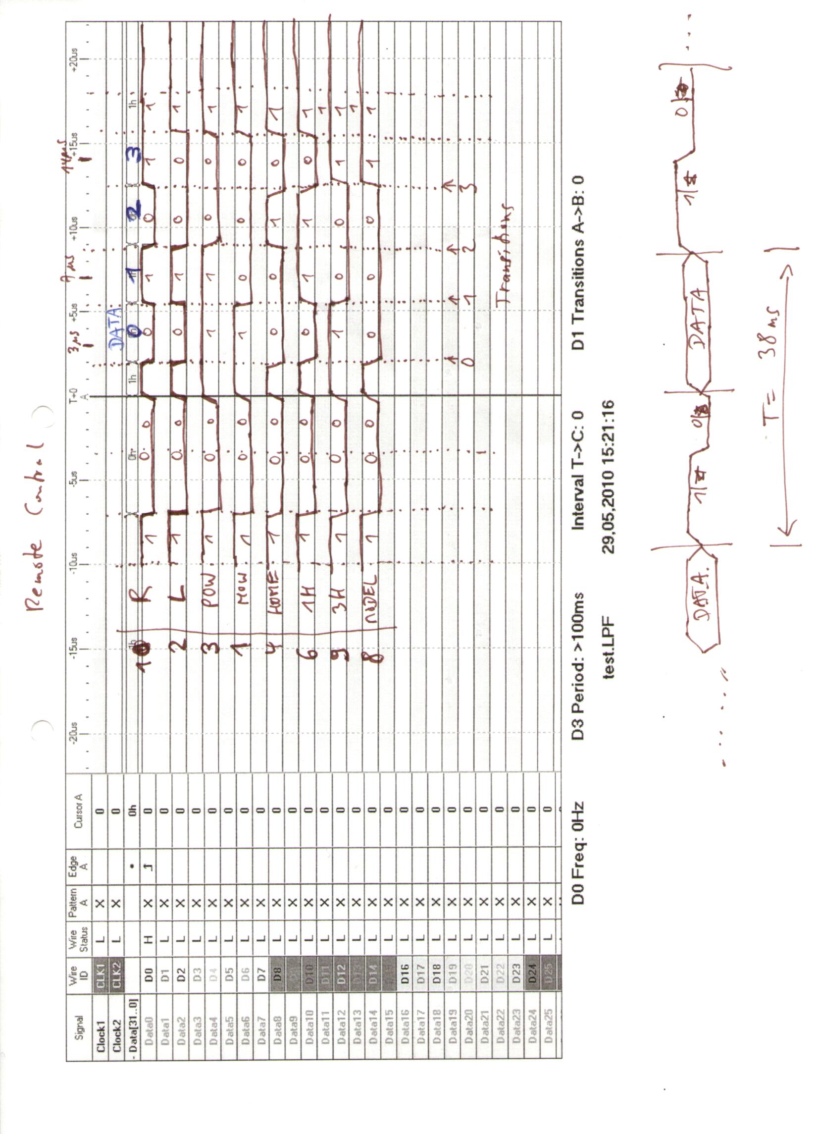
-Remote control decoder MCU: STC12C2052AD (sends remote control key data to main MCU, see protocol below)
-Induction unit quad op amp: LM32 (for induction loop inductor amp)
-Optical roll ball sensor: HT RBS33 (theta=45 degree , switches off mowing motor above theta degree)
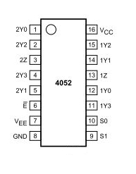
-Dual 4-channel mux/demux: 74HC4052D (to read in induction loop inductors and battery sense/rain sensor)
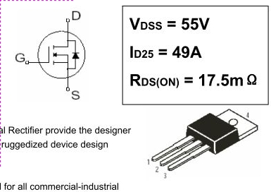
-Power MOSFET: IRFZ44N (for mowing motor)
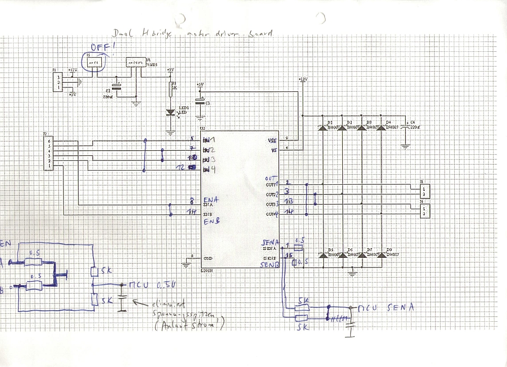
-Full bridge driver: L298N (for the left and right motors) – also see example schematics here
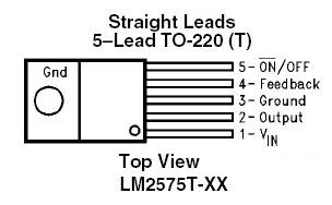
-1A step-down simple switch voltage regulator: LM2575S (for main board voltages)
-Solid state amp: SR840 (for mowing motor)
-Timer: NE555 (for IR modulation?)
-Dual op-amp: LM358 (for induction loop inductor)
–
2. Adding an ultrasonic sensor (Arduino hack)
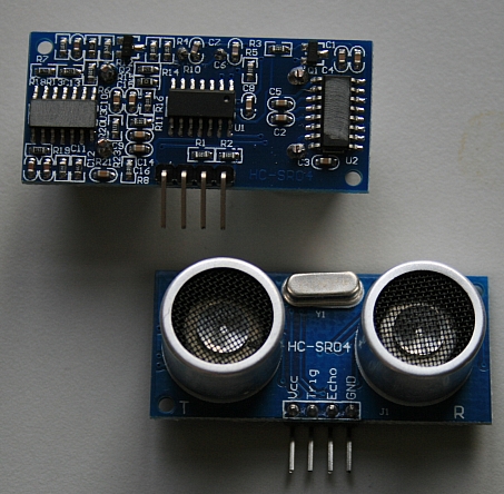
An ultrasonic distance sensor greatly helps to avoid bumping obstacles (or to drive into shrubberies). We use the HC-SR04 as it’s easy to use (you can find these boards on eBay).
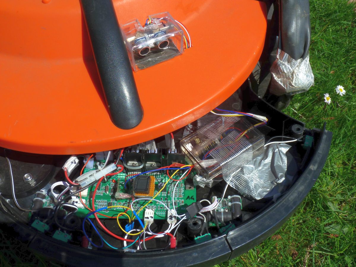
This hack is universal – actually, you can add it to ANY robot mower. The good thing is you can keep the robot’s stock MCU firmware, and it’s easy to add: Just add another two wires to the front bumper push buttons, and your Arduino will simulate one of the bumpers (by switching the bumper signal to LOW) when the ultrasonic distance sensor detects an obstacle!
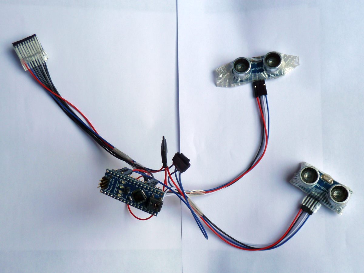
We use an Arduino Nano board for the controller as it’s very popular and very easy to program.
Arduino <—> robot wiring
Pin 7 <—-> robot left bumper signal pin (P8.2, see below)
Pin 8 <—-> robot right bumper signal pin (P8.4, see below)
Pin 12 <—-> ultrasonic board (trigger pin)
Pin 11 <—-> ultrasonic board (echo pin)
VCC <—-> robot +5V (P6.1, see below)
GND <—-> robot GND (P6.4, see below)
Robot bumpers pinout (P8) is (left-to-right):
1-GND
2-left bumper signal pin
3-GND
4-right bumper signal pin
Robot P6 pinout is (top-to-bottom):
1-VCC (+5V)
4-GND
(the first photo shows the version for the Ambrogio L50 robot mower using two ultrasonic sensors)
For debugging purpose, you can add a piezo speaker:
Finally, you can see everything in action (NOTE: In this video, there is no perimeter that can stop the robot, it is only the ultrasonic sensor that can stop it)
NOTE: I have not tested yet how the ultrasonic sensor can be automatically deactived when the robot drives into the charging station – I’m not using any perimeter with this robot, so at least it works without perimeter…
For Arduino code, see resources section further below.
Hardware/software used for the hack:
A microcontroller that is easy to program: I did choose the Arduino Nano for all my hacks. You can find the Arduino Nano controllers on eBay (8-10 EUR)
Ultrasonic sensor board HC-SR04 – you can find those board on eBay (5-7 EUR)
3. Replacing the stock MCU firmware (ATMEGA hack)
Replacing the stock MCU firmware requires to write a new firmware, and I did choose the Atmel ATMEGA-168 (on a ready myAVR board MK2 USB) as a replacement for the original 8051 MCU.
The first step is to desolder the MCU socket as you can see on my robot mower board .
Here you can see how I managed to connect my Atmel MCU to the old MCU socket (using some DIY adapter). Alternatively, you can directly connect the individual board pins to your Arduino board using 1-pin-cables (you can find them on eBay).
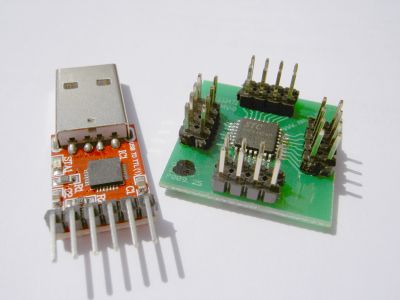
After a while, I noticed that I need something more fancy to upload my new custom software revisions into my mower while sitting comfortable in a chair meters away: a Bluetooth module! The bluetooth module extends the ordinary ISP RX/TX serial line (RS232) and also allows me to monitor sensor data and robot state changes (and believe me, this feedback is absolutely necessary for debugging your code…)
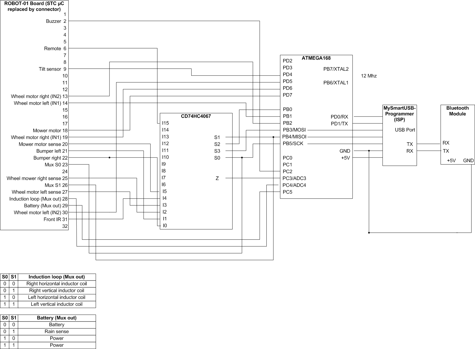
So this is my final system today:
Original board <==> ATMEGA168 <==> ISP (TTL UART) <==> Bluetooth module <~~> PC (Bluetooth dongle)
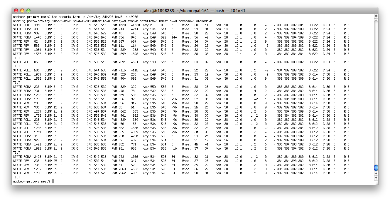
I upload new software builds into the mower via Bluetooth and the serial data of the mower is transmitted via Bluetooth too.
My latest software periodically displays the state of the mower (state, state time, bumper states, IR state, inclination sensor, motor PWM, motor PID controller wxy, motor current, induction coins values, battery state, rain sensor):
ATMEGA168 microcontroller (16K flash, operating at 5V)
12 Mhz oscillator
Bluetooth module BTM220 , an inverter 74HCT14N for level shift conversion (because my BTM220 operates at 3.3V, I needed a level shift conversion to 5V)
Multiplexer CD74HC4067 (to reduce the number of required pins at the microcontroller)
Two photo sensors to measure the wheel movement (wheel left/right balance control) – later I replaced this by a declination sensor which works great too
For ATMEGA code, see resources section further below.
–
4. Adding a PID controlfor the wheels
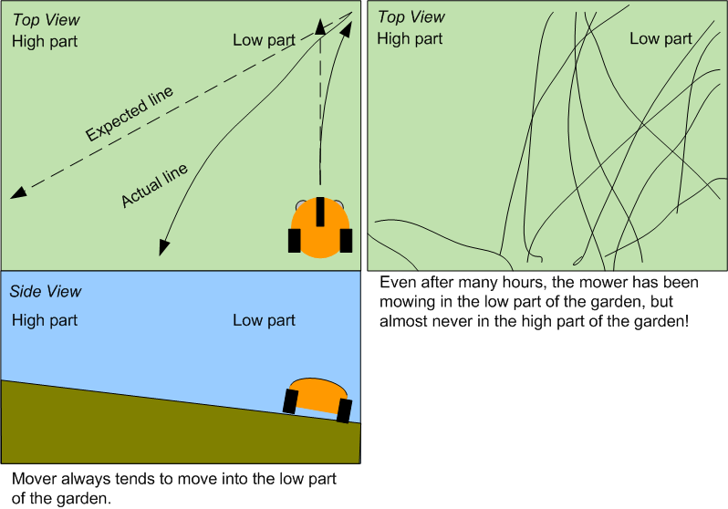
After purchasing, I noticed the robot has a small problem: when moving from the lower part to the higher part of my garden, it doesn’t move a straight line – it makes circles of 90 degress and less (due to the heavy lead acid batteries my mower is using) …
(Also have a look at my mower simulation that demonstrates the difference ‘lawn with and wihtout slope’).
So I decided to add some software PID controller to it to control the left-right wheel balance 🙂 and it solved this specific problem (see videos with and without balance controller).
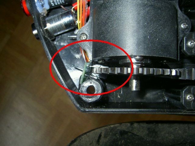
And here you can see how I added photo interruptors (LTH301-07) for the left and right motors to measure the wheel movement (for the left-right wheel balance control):
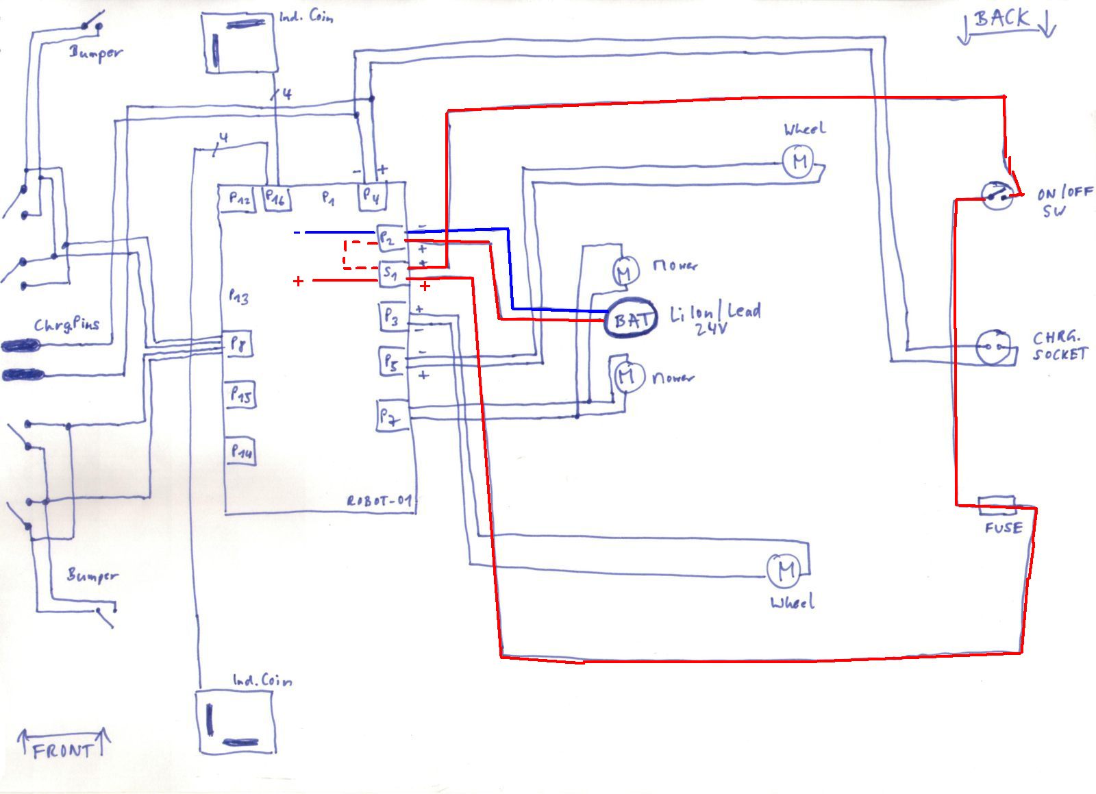
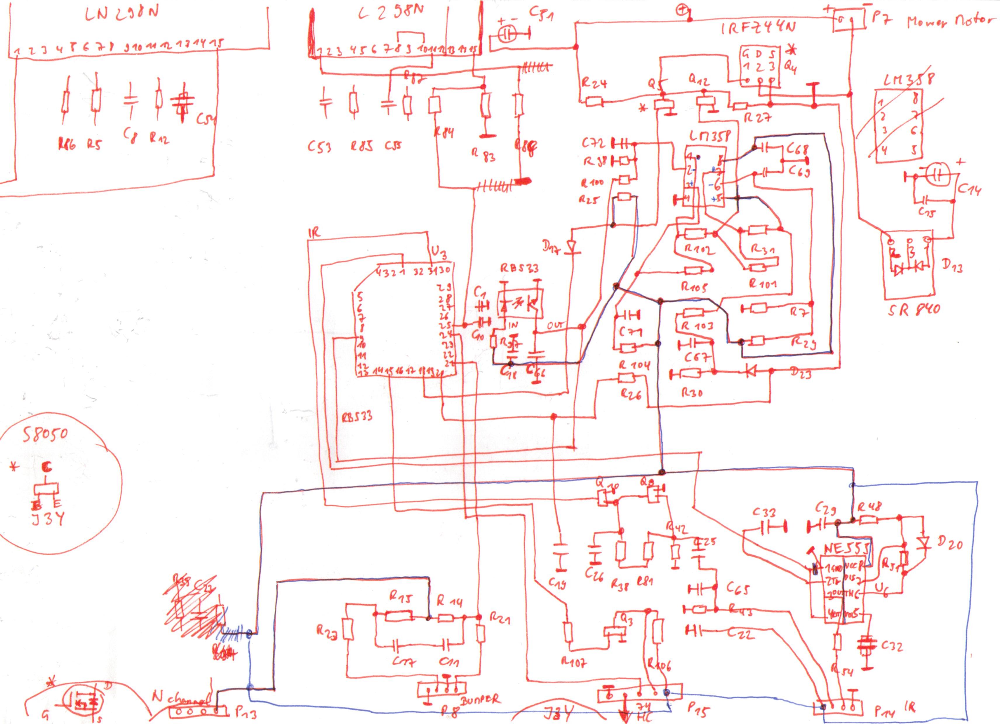
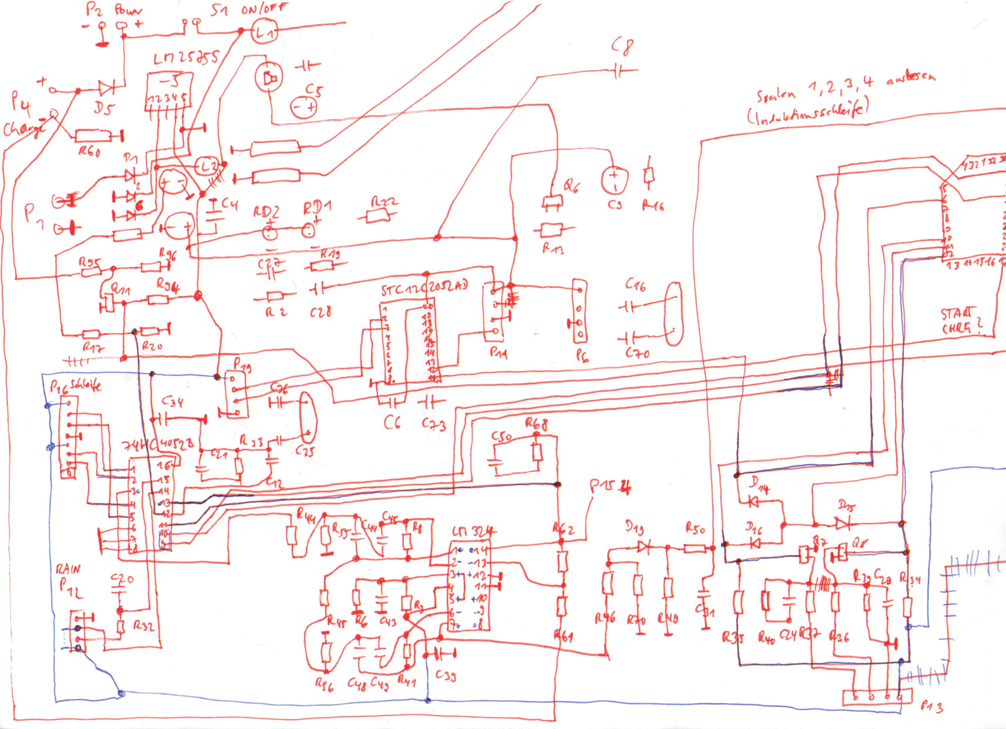
My pseudo-schematics (1), (2)
(Warning: always measure and verify using your own board – manufacturers often change their layouts and make adjustments, and without measuring you may damage your own board!)
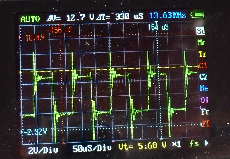
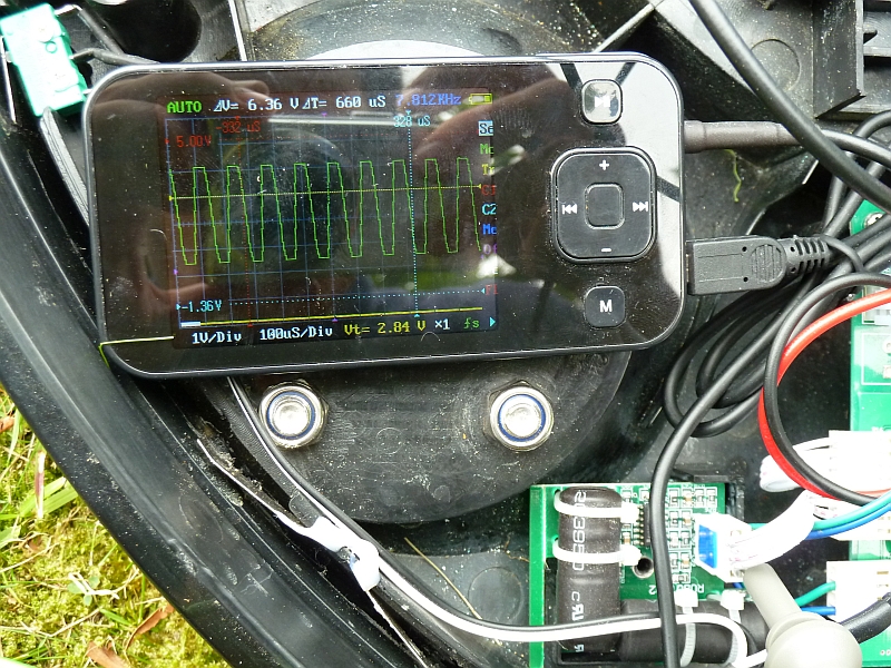
Charger induction loop signal (measured at induction loop cable output)
Induction loop coil signal (measured at induction coil connector)
Connector pinout: +5V, GND, vertical coil output, horizontal coil output
ATMEGA robot mower code (code also describes the MCU socket<->ATMEGA168 wiring – Warning: don’t expect this code to work at once in your own configuration – you’ll need to study schematics, your MCU specifications and much more to get it working!)
Pinout of ICs LM2575S(voltage regulator) IRFZ44N(N channel power MOSFET) LM324(operation amplifier) 74HC4052(multiplexer) L298N (motor driver) STC12C5410AD(MCU)
STC5406AD (MCU)
–
6. External resources on the Internet
Wiring diagram for the updated version of the robot (additional security board) which turns-off the mower when the front wheels have no contact
Induction loop receiver board schematics (and more) at robi2mow
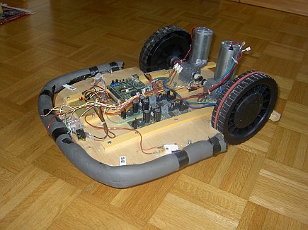
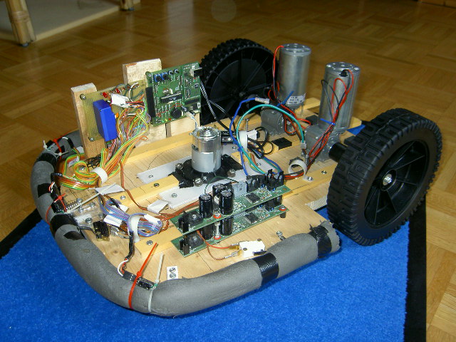
Wouldn’t it be nice to lie in the sun and have a robotic mower mow the lawn (and do the boring work)? Well, at least this is the aim (among other aspects as learning more about designing such systems) of this project…
A) Mechanics
Two wheels of a seed vehicle
Two office chair front wheels
Two DC motors motors (12V, 40W) with gear (23:1)
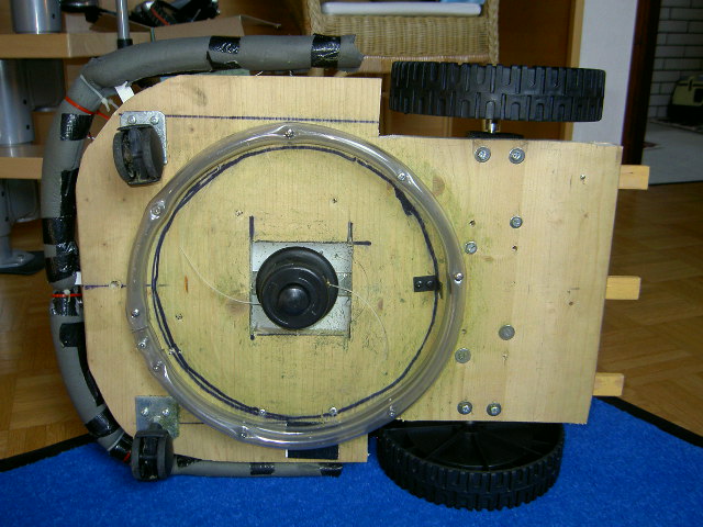
B) Mowing unit
DC motor from a 18V battery lawn trimmer
C) Controller
Microcontroller board ATMEGA168 (myAVR, 50 EUR) for reading the sensors and controlling the motors (two rear motors).
D) Sensors
Three Sharp IR sensors to detect near obstacles
RGB color sensor to detect non-lawn/lawn areas (no need to build a virtual fence in your garden!)
Bumper with three micro switches
E) All other parts
A wooden board (38 x 53 cm) for assembly of everything
Two gel-lead batteries (2 x 12V, 10Ah)
F) First version (without mowing unit), without sensors
Click here to see video (9 MB) which shows this mower prototype in action (indoor) 🙂 G) Second version – now with sensors and mowing unit!
The color sensor is working – the RGB color value is measured periodically and then converted into HSV (hue/saturation/value) color model. A first test with real lawn shows it can detect areas with a green color very precisely. For testing the algorithm, the first goal was to keep the robot on the blue piece of carpet – it successfully stayed on there, even after ‘mowing’ for 30 minutes!
A blog on projects with robotics, computer vision, 3D printing, microcontrollers, car diagnostics, localization & mapping, digital filters, LiDAR and more
