The problem
You want to transmit a (constant) signal from sender to receiver in a noisy environment with a minimum of energy at the sender. Constant means you know the signal to be transmitted, so it’s not arbitrary data (as you’ll see later, of course you can send arbitrary data too using the method described below by sending two different signals).
Abstract
Have you ever thought how a (relative weak) GPS signal gets through the noisy environment – a distance of 18,000 km – from the satellite to your GPS receiver? The answer is: using a software-based ‘matched filter’ (aka optimal filter). Do you think you can use the same principle with an Arduino? The answer is: yes!
Introduction
For the Ardumower project, we had to solve the problem to detect a buried wire fence (BWF) signal in a noisy environment where the noise is 10 times higher than the transmitted signal. What does this mean?
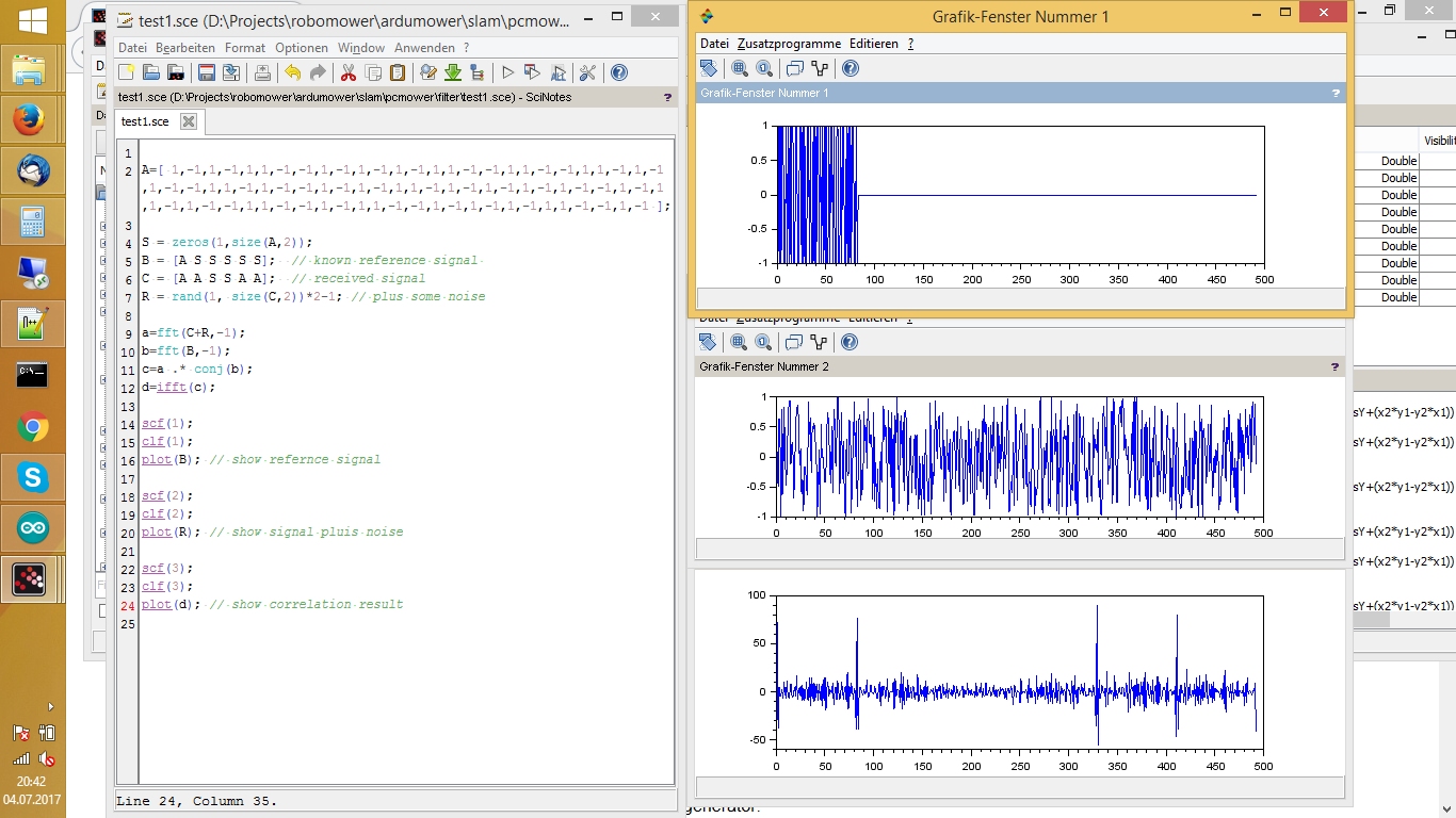
Let’s assume you can generate this constant bit sequence (also called samples) in your sender:
1,1,-1,-1,1,-1,1,-1,-1,1,-1,1,1,-1,-1,1,-1,-1,1,-1,-1,1,1
where ‘1’ means a high pulse, and ‘-1’ means a low pulse. The signal has an amplitude of 1. The generated signal would then look like this:
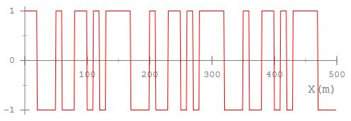
In the plot, the signal repeats three times (actually you can see the start of repeating a 4th time). The signal we did generate is ‘pseudo-noise’ because we did choose a constant sequence (1,1,-1,-1,1,-1… etc.) that looks like random from a statistics point of view.
Now let’s assume your environment adds a noise that is 10 times higher than your signal, it will have an amplitude of 10. Also, let’s assume it adds random noise, so not a certain frequency or frequency band is noisy but all frequencies of the signal are noisy (aka white noise) – So this is what you receive in your receiver:
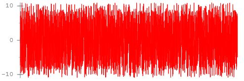
Do you think it’s possible to clearly detect the sender’s signal in such a noisy environment? Using a ‘digital matched filter’ is is possible. This is how the the output of the ‘matched filter’ result will look like:
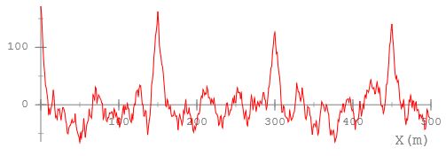
The peaks are where the start of the signal was detected. As you can clearly see, the matched filter tells us that the signal repeats four times and where.
How does it work
The matched filter works by ‘moving’ the known signal (constant template signal) over the received input signal, sample-by-sample, and computing the correlation each time the template is moving over the the complete input signal (so, it is relative CPU consuming). A the position where the template signal and input signal are ‘in phase’, the correlation has its peak (template matches best). Because the template signal is ‘pseudo-random’ and a ‘long sequence’, the filter still works when high noise is added.
Trying out and tuning
Before I started implementing the matched filter, I wanted to experiment with it, so I did write a simulator where you can generate a user-defined signal, add some noise to it, and see how well the matched filter performs.
Here’s the link to the matched filter simulator:
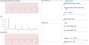
There are some pre-defined constant signals in the simulator that are a good candidate for the matched filter to be used for the template signal (so the signal to match):
- pseudonoise4_nrz (short sequence)
- pseudonoise5_nrz (longer sequence )
- pseudonoise7_nrz (even longer sequence)
- pseudonoise4_pw (short sequence – using different pulse width coding for 1 and -1)
- pseudonoise5_pw (longer sequence – using different pulse width coding for 1 and -1)
- pseudonoise7_pw (even longer sequence – using different pulse width coding for 1 and -1)
The NRZ coding uses a ‘high’ pulse for 1, and a ‘low’ pulse for a -1, and a fixed pulse width.
In the PW coding however, the signal always toggles (hi,lo,hi,lo,hi,lo etc.) and uses a long width pulse for a 1 bit, and a short width pulse for a -1 bit. For the Ardumower project, we could not use the simple NRZ coding as the signal cannot be kept too long high on the wire, so the PW coding always gives us a high/low change.
While experimenting, you can see that:
- The longer the signal, the better the matched filter performs
- The more ‘random’ the signal, the less false matches you get (the better the matched filter performs)
Back to Ardumower: Using a matched filter with Arduino
Sender
For our BWF (buried wire fence) sender, we did generate the signal using a motor driver and an Arduino. The Arduino generates the pseudo-noise signal sequence, and the motor driver brings it onto the BWF wire.
Basically, the sender is a timer that toggles the motor driver according to the signal sequency. Nothing fancy.
Receiver
For the receiver, we did use a coil to receive the signal, an OP amplifier (LM386) to amplify the signal, and an Arduino to ADC-sample the signal, and filter it with the matched-filter described above.
The ADC sampling is done using Arduino ADC free running mode. Nothing fancy. After the caputered ADC samples are in a buffer, they are processed by the matched filter like this:
...
convFilter(matchSignal, signalsize, samples, out, BUFSIZE-signalsize);
...

// digital filter (cross correlation)
// http://en.wikipedia.org/wiki/Cross-correlation
// H[] holds the signal to look for (also called filter coeffs)
// ip[] holds ADC sampling buffer (length > nPts + M )
// op[] is filter output buffer
// nPts is the length of the required filter output data
void Perimeter::convFilter(int8_t *H, int16_t M, int8_t *ip, int16_t *op, int16_t nPts){
  int16_t sum = 0;
  for (int16_t j=0; j<nPts; j++)
  {
      sum = 0;
      for (int16_t i=0; i<M; i++)
      {
        //sum += H[i]*ip[subSmp*j+i];
        sum += ((int16_t)H[i]) * ((int16_t)ip[j+i]);
      }
      op[j] = sum;
  }
}
Arduino example code…
So you want to try out the code? Then take a look at the Ardumower’s perimeter code in the project SVN repository, it contains real-live code.
Optimizing further
The correlation above needs O(n^2) and can be optimized O(n*logn) if using the FFT:
Check out Barker Codes — they are pseudorandom sequences like you are using, but specifically ones which have minimum energy outside the autocorrelation peak. Should slightly improve performance over purely randomly chosen codes. http://en.wikipedia.org/wiki/Barker_code