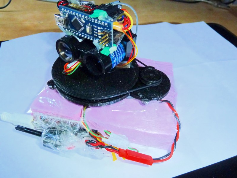
This project describes step-by-step how you can build yourself a 360 degree Lidar for realtime outdoor mapping and position tracking on that map (aka ‘localization‘). This idea is also called ‘SLAM’ (simultaneous localization and mapping). We use inexpensive parts for this Lidar, so this is probably the cheapest 360 degree realtime Lidar you can build!

Features:
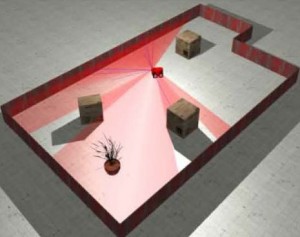
- 360 degree, realtime operation (important: world ground must be flat – for a 3D world, see section at the page bottom)
- sensor: LidarLight v2 (500 Hz measurements, approx. 1cm precision)
- field of view (horizontal): 360 degree
- range: 40m, indoor & outdoor
- rotation speed: 1-10 Hz (can be adjusted by potentiometer)
- diameter: 60 mm
- 3d printed chassis (so you need access to an 3d printer)
Parts needed:
Note: all parts will be available as a DIY kit in this shop soon.

- Lidar Lite v2 sensor (alternatives: TeraBee TeraRanger One, LeddarTech Leddar One Sensing Module)
- Arduino Nano
- serial/USB converter
- DC motor (PMDC: 1.18mN*m, 24.4mm diameter, 2000 rpm, 2mm shaft, 5v, 170 mA load)
- ball-bearing (6807 ZZ 61807: inside diameter 35mm, outside diameter 47mm, height 7mm, steal sealing ZZ)
- slip ring (LPM-04A: outside dia 12.5mm, flange dia 24mm, length 15mm, 4 wires)
- rubber gasket (NBR70 – 70mm diameter, thickness 2mm)
- micro photo sensor (2mm opening, Omron EE-SX1108)
- mini screws (2mm diameter, 8mm length)
- 2 resistors (780 Ohm, 33K), 1 capacitor 680 uF
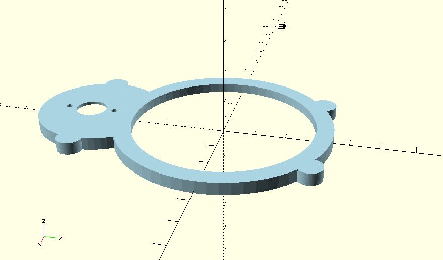
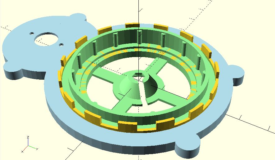
- base plate (3D print), layer height: 0.3 mm

- bearing base (3D print), layer height: 0.3 mm
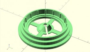
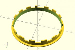
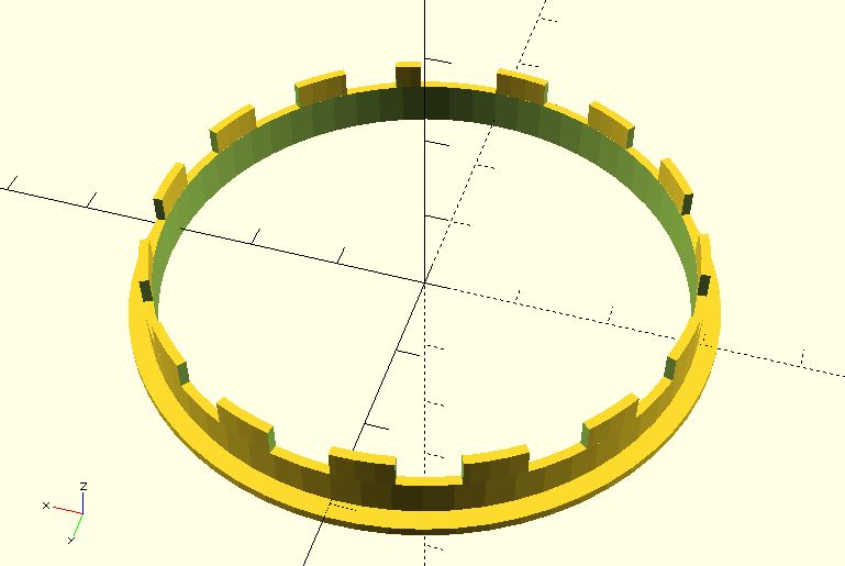
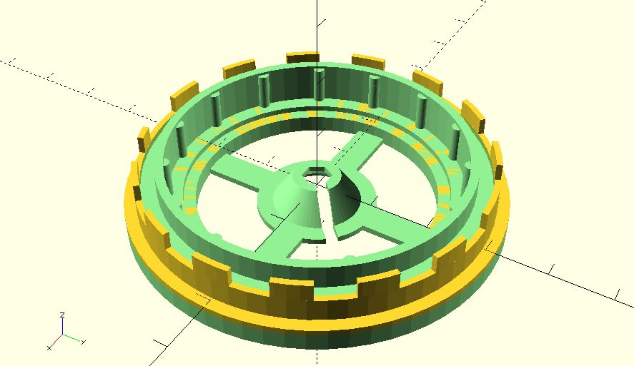
- encoder ring (3D print), layer height: 0.1mm
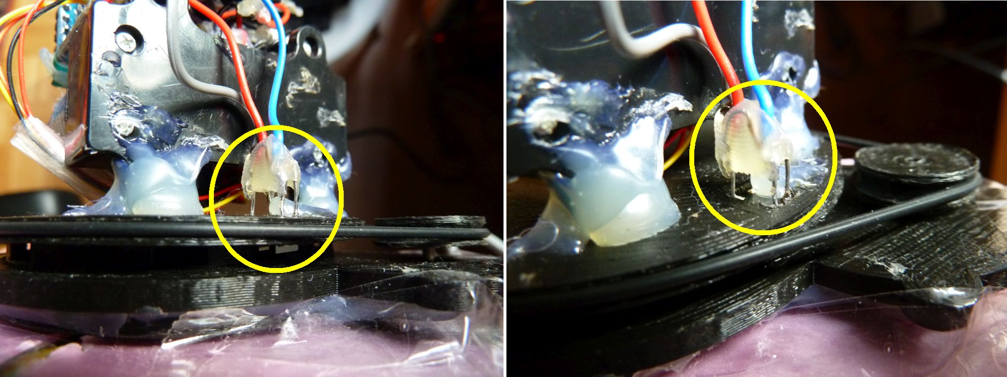
The encoder ring has 15 pits, one pit is shorter and allows to detect zero position. Each pit triggers a voltage transition (0/1/0/1/0/1 etc.) in the light barrier, indicating the next 12 degree step. Using a timer, the degree steps in between (0-12 degree) can be computed.
- motor ring (3D print), layer height: 0.1mm
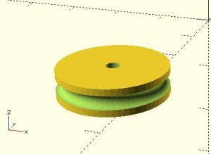
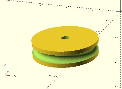
- disc base (3D print), layer height: 0.3mm

- disc lidar holder (3D print)
to be continued…(your ideas?) - disc cover (3D print)
to be continued…(your ideas?)

Assembling:
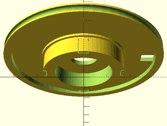
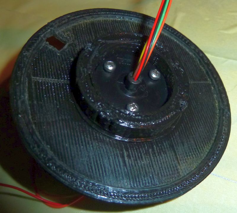
1. Stick encoder ring and bearing base together:
2. Add both to base plate (hot-glue at underside):
3. Make sure that your bearing runs smoothly (can make one rotation after driving it with one finger). My bearing had too much grease inside, so I had to disassemble the bearing and remove the grease. Assemble bearing, motor and wheel. The motor should run clock-wise when connected to +5V and GND. If not, swap the connector wires.
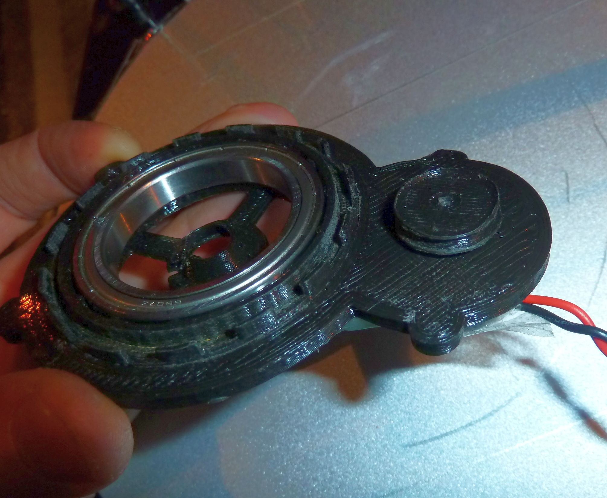
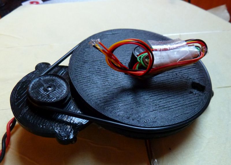
4. Mount slip ring on disc base with screws, stick disc and base together, mount screws at disc bottom side.


5. Mount Lidar, Arduino, Micro-photosensor (e.g. using hot-glue)
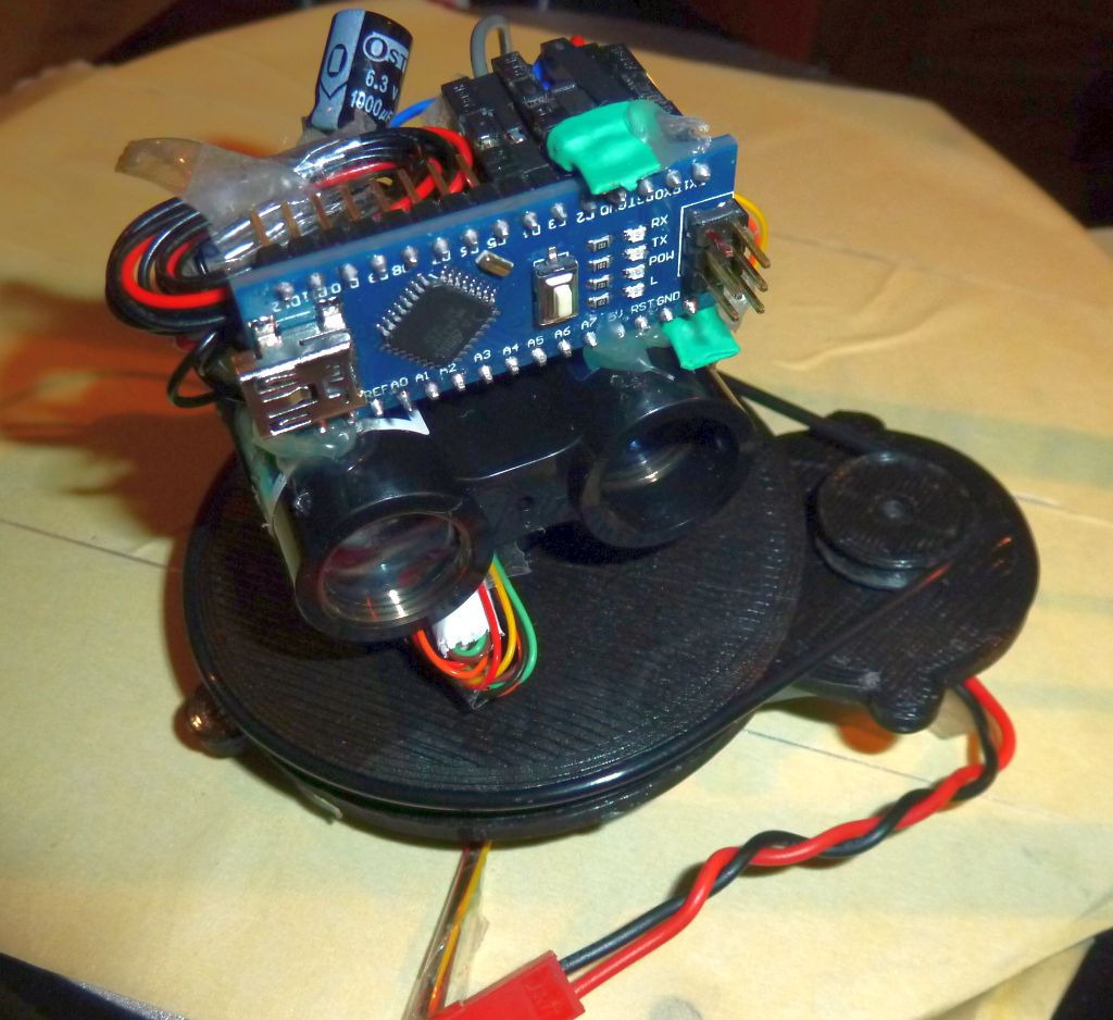
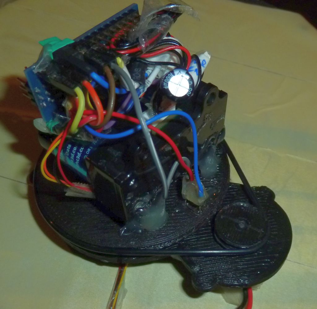
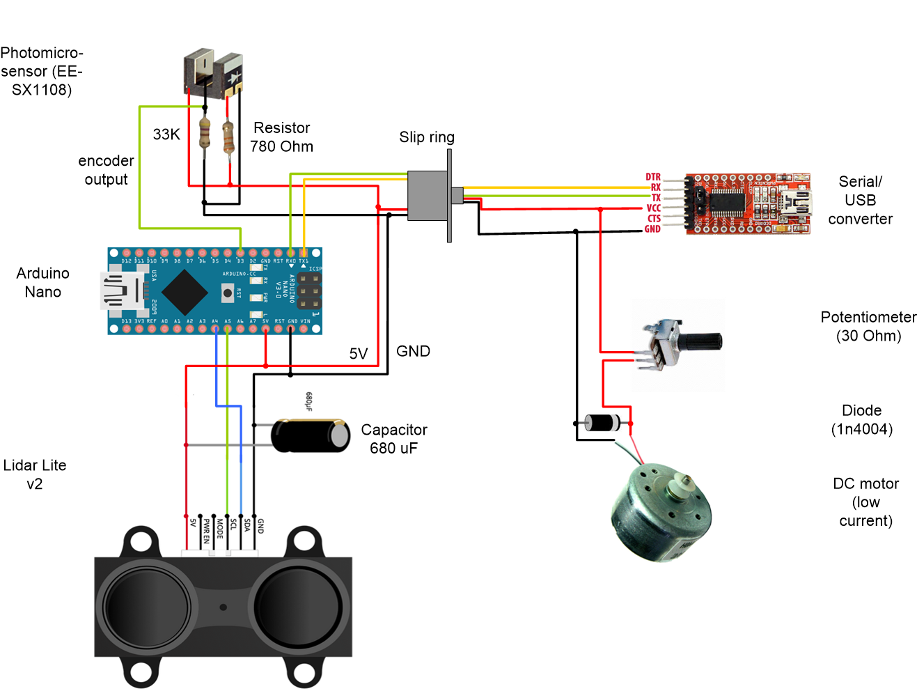
6. Wire as shown below:
Note: Keep soldering time for the photomicrosensor short (max. 3 seconds), otherwise you risk to damage this sensitive component.
7. Test mechanics
Make sure that the disc can turn with a constant speed (and not erratic). If the speed is not constant, the lidar will not work properly. My 3d printed parts were not very precise, so I had to rasp all parts so they fit and and do not rub.
8. Flash Arduino code
Since we are using the serial/USB converter for flashing the Arduino, resetting the Arduino automatically will not work. Press ‘Upload’ in the Arduino IDE and then press the RESET button on the Arduino to initiate the code upload.
9. Downloads:
- LIDAR base parts (STL)
- LIDAR disc (STL)
- LIDAR OpenSCAD code
- Arduino Nano code
- LIDAR visualization and SLAM (mapping & localization) executable for Windows
- LIDAR SLAM code
- ROS node (graulidar.py)
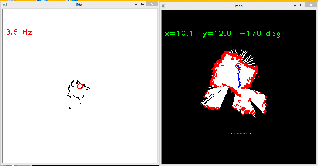
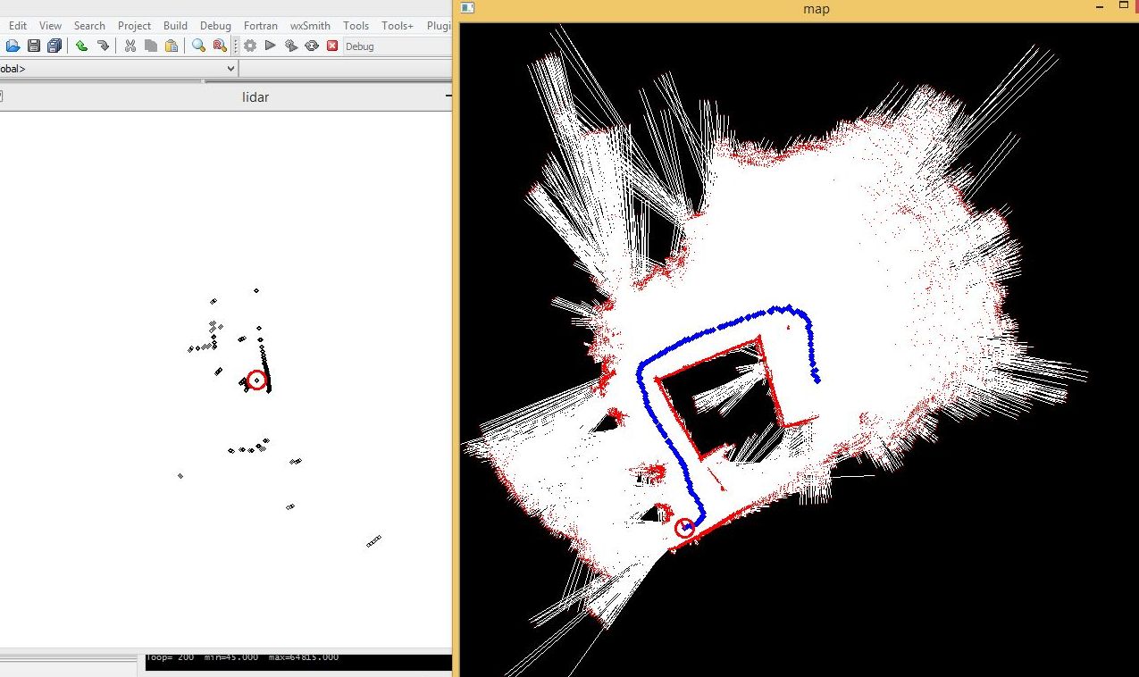
10. Example usages:
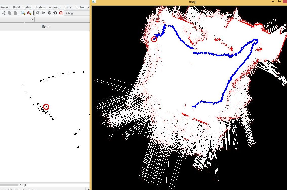
- SLAM (Simultaneous Localization and Mapping). Using a SLAM algorithm (e.g. Hector SLAM), you can create maps (mapping) and estimate your position in those maps (localization).
usage slam.exe <dev> <mres> <mpx> <dpx> <hlev> <hdths> <haths>
  dev     lidar device path (\\.\com3)
  mres    map resolution meters (0.1)
  mpx     map size pixels (600)
  dpx     display pixel size (1.0)
  hlev    hectorslam res levels (3)
  hdths   hectorslam distance threshold (0.5)
  haths   hectorslam angle threshold (0.9)

example indoor: slam.exe \\.\com3 0.1 200 3 4 0 0
example outdoor: slam.exe \\.\com3 0.1 600 5 4 0 0

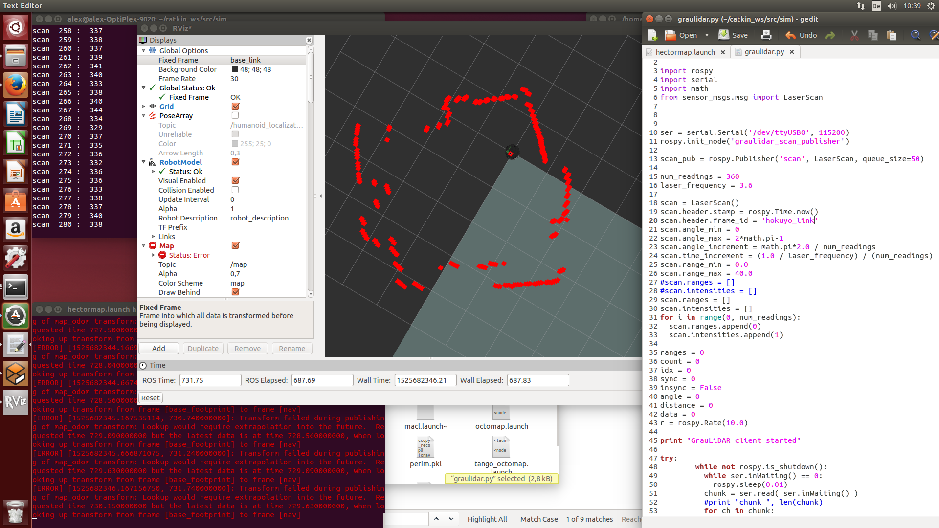
As ROS node:
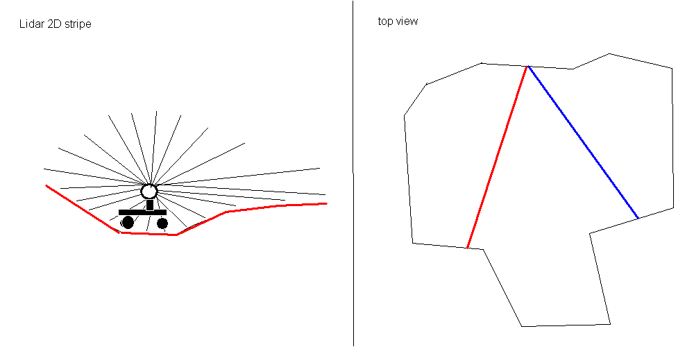
11. DIY 3D Lidar
Could this Lidar work in a 3D world (with sloped ground)? Well, by operating the 2D lidar in a vertical orientation. Then we get a 2D stripe of the world (including the current position on that 2D stripe) that we could use for mapping and localization – A compass would help us to estimate the orientation of new stripes (blue stripe).
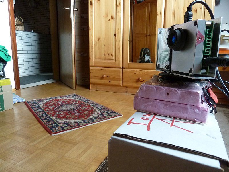
For a realtime test I’m using a 2D LeddarTech M16 Lidar (45 degree, 16 segments, 100-1000 Hz) monted on a servo:

I’m using MeshLab for visualization – use ‘Normals, compute’ in MeshLab to compute normal vectors for the faces.
LeddarCDemo
Example measurements
Further topics: hectorslam (2.5d slam), rgbdslam (3d slam), octomap (3d mapping)
Very nice work. I look forward to seeing if you can successfully use this as a real-time navigation tool. I was unable to get mine to work properly, as even at 300 Hz I was unable to make steering adjustments quickly enough to keep my robot from running into walls 🙁
Regards,
Frank
Great project,
Do you have any estimate when the DIY kit will be available?
Hello Simon,
The DIY kit should be available in January 2016 (hopefully, PulsedLight LLC will again produce another bunch of Lidar Lite v2 sensors until then).
Regards,
Alexander
Really great project !
I want to try to do the same thing but I cant seem to be able to find the mesurements on the bearing and rubber gasket? Would be great if you could post them 🙂
Regards
Daniel
Hello Daniel, I have updated the measurements on the Blog – I hope it should be clear now? 😉 Regards, Alexander
Thanks ! 🙂
One more question, is there any specific resoning behind having the arduino on the spinning disc ? Would having the arduino beneath the disc, connected to the LIDAR through the slipring work as well ?
Regards Daniel
Hello, I just wanted to save one wire for the slip ring, so (TX,RX) when Arduino on top instead of (SCL,SDA,ENC) needed for Arduino beneath the disc. It should work beneath as well (although I haven’t tested this). Regards, Alexander
Alright 🙂 Thanks again for awnsering, really great work 🙂 I have ordered the slipring, bearing and rubber gasket from ebay 🙂
Regards
Daniel
Hi, I hate to get picky but.
1) Where is your schematic? (not fritzy)
2)How much current does the assembly consume? (Will it run on PC USB?)
3)Where on fritzy is your 5V supply and at what current?
You have listed features but no specifications.
Tom
1) I don’t have one – I hope it’s not too difficult to read the fritzy…
2) The PMDC motor takes 170 mA load – yes, runs on USB
3) The 5V is coming from the USB TTL adapter (VCC) and going to the Arduino 5V pin, max current 200mA
Hey,
I am working on a similar project. I also use a ir distance sensor. According to the datasheet I can get a sampling rate of about 20hZ.
So I was wondering what sensor you used to get that sample rate, and what is your fastest sample rate?
Ruben
The LidarLite IR sensor has a sample rate of 1000 Hz. For different rotation rates, you get different samples per rotation (I could run them all):
rotation rate 10 Hz => 100 samples per rotation
rotation rate 5 Hz => 200 samples per rotation
rotation rate 1 Hz => 1000 samples per rotation
The lower the rotation rate, the less suitable for realtime applications. The higher the rotation rate, the lower the resolution. Using 2-5 Hz, I did get good results.
Hey my friend and I were trying to make a 2d map like you did. We couldn’t get the map to work it was not responding. We are not sure what to do . Do you have any ideas? Also what do we do with the LIDAR SLAM code, we downloaded it and did not know what to do with it
Hello ,
I want to this localization with Rviz using ROS .I have urg-04lx laser scanner . How can ı do this .Please help me .
Hello! I love this build and you are a saint for releasing the code, thank you! I have made myself a variant of it and have the code running. The mapping appears to work but does suffer a little bit with noisy / returns. Some points seem to jump around somewhat, I can see something similar in the ardumower video. Did you manage to find a way to get stable, consistent outputs? Or does it not affect the SLAM too badly? I am hoping to more fully test SLAM out shortly once I have a mobile platform completed to mount it on!