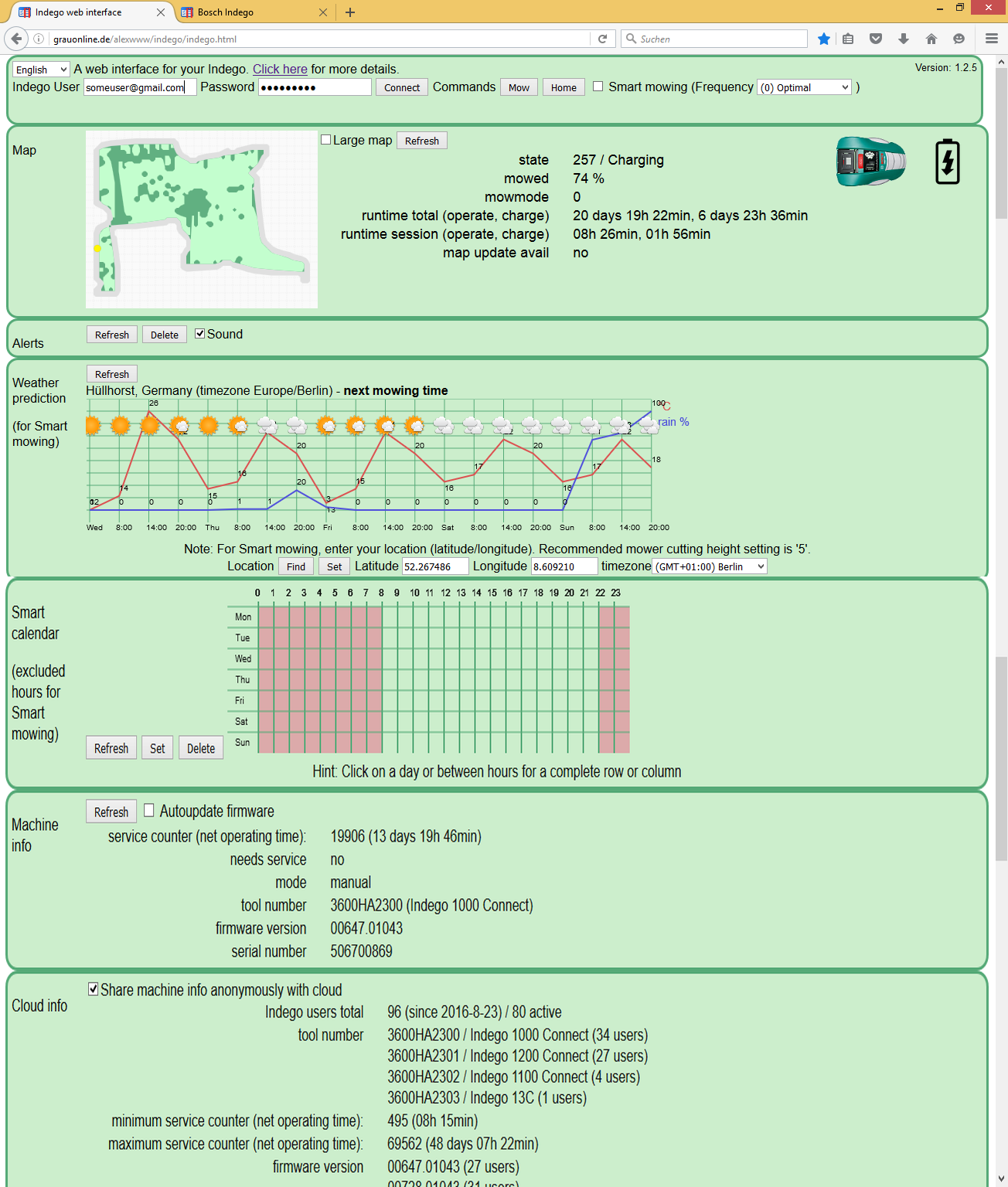
Update 2016: Web interface for your Indego (click here)
How to use: insert your Indego account user (e.g. e-mail address) and password, press connect and monitor your Indego. Why is it safe to enter user account data into this web interface? It is safe because this web interface is 100% Javascript and it is executed locally on your machine (and your account data is only stored locally in your web browser). You can verify that your machine is establishing a secure connection to the Indego server (and no other server): In Firefox, press CTRL+SHIFT+K – in Chrome, press CTRL+SHIFT+J and then click on ‘network’ to verify yourself that it this web interface is secure (does not establish any other connections).
Update 2015: Bosch Indego Connect
This page describes some internal details of the robot mower “Bosch Indego”. The Indego is the only (known to me) robotic mower that …
1. can locate where it is, and so
2. navigate to a specific location in the garden.
One can literally look the Indego over your shoulder by looking into the generated maps, and so learn more about it. Here is an animation of the mapping (Click to play):
It is immediately apparent that the map is already complete at the first perimeter loop run and that the map is not corrected in further mowing sessions. I have placed the Indego map over an estate map and areal photo.

The dark grey line is the map border. You can see that the orientation of the map border sections is very accurate but the distances are not. The reason is that the sensor for measuring the orientation (Gyro + Compass) is very accurate, but the sensor for measuring the distances (odometry) is not particularly accurate.
Operation
One can only speculate about the exact algorithms of Indego, probably it works as follows:
Sensors:
-perimeter signal strength (2 coils)
-motor encoders/odometry (measures traveled distance/cm), accuracy depending on terrain 70-95% per meter
-gyro and compass (compass is tilt corrected by acceleration sensor), measures course/orientation , accuracy <1 degree
Mapping: after installation, the robot travels along the perimeter wire and generates a map of the garden.
Localization: the short-term position is estimated by odometry – if the Indego hits the perimeter, the estimated position is corrected. To improve the position estimation, the perimeter field strength is probably used and stored in the map ( ‘particle filter/Monte Carlo localization’). Sometimes, the Indego has no estimation where it is on the map (e.g. if you stop it manually) – then it travels along the perimeter wire and computes a ‘correlation’ with the map to find out its position. Often, a short perimeter section is sufficient for a secure position estimation (=high correlation with the map).
Gyro calibration: Every 3.5 minutes the Indego stops (turns of all motors) and “calibrates”. Then the gyro offset (caused by temperature variations) is measured and probably also the absolute orientation (via compass), and so the gyro orientation is corrected (as the summing up of the gyro values will otherwise drift after a few minutes).
Compass calibration: Sometimes the Indego simply rotates at a fixed position – it is quite possible that it is calibrating the compass during this time (like a sailing ship that calibrates its compass by sailing a circle). Calibration a compass means finding the minimum/maximum values of each compass axis (x,y,z).
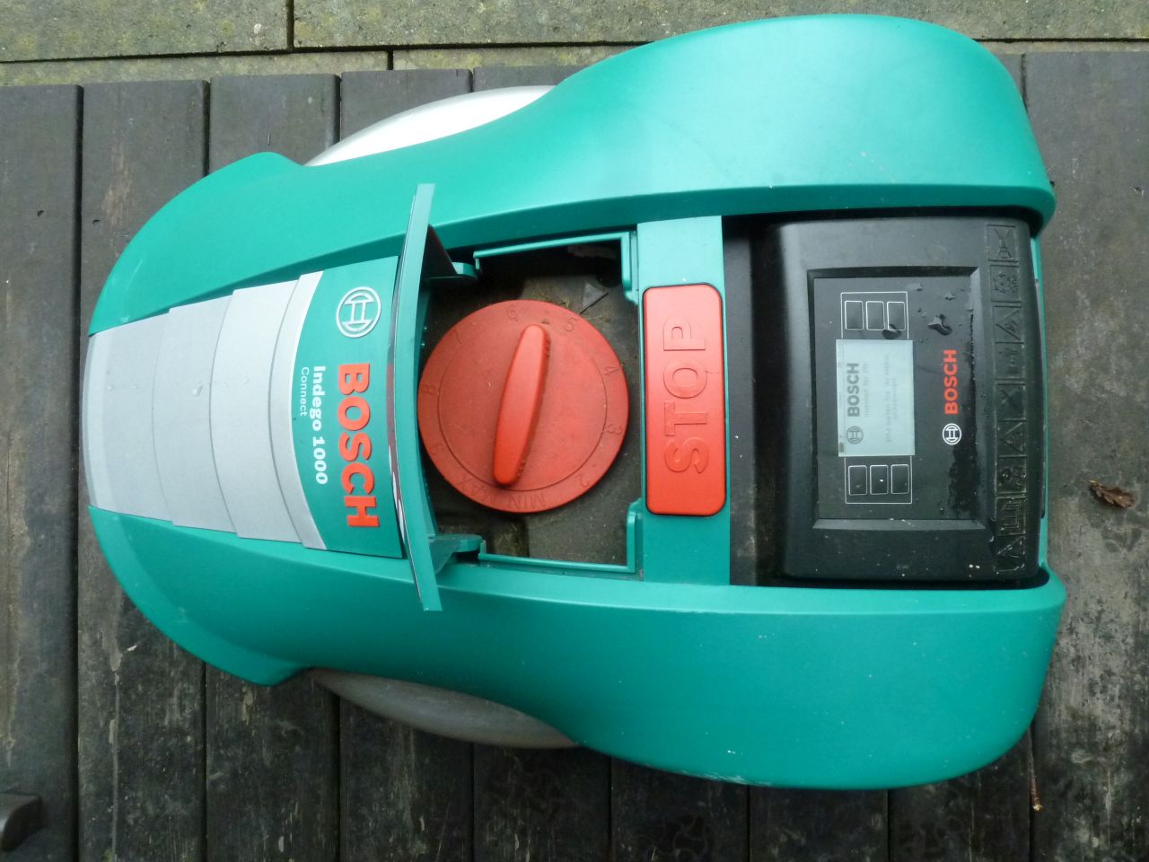
Overall view
Models:
3600HA2100 – —, 0V/–
3600HA2101 – Indego, 230V/EU
3600HA2102 – Indego, 230V/EU
3600HA2103 – Indego 800, 230V/EU
3600HA2104 – Indego 850, 230V/EU
3600HA2200 – Indego 1300, 230V/EU
3600HA2201 – Indego 1300, 230V/EU
3600HA2300 – Indego 1000 Connect, 230V/EU
3600HA2301 – Indego 1200 Connect, 230V/EU
3600HA2302 – Indego 1100 Connect, 230V/EU
3600HA2303 – Indego 13C, 0V/EU
3600HA2304 – Indego 10C, 0V/EU
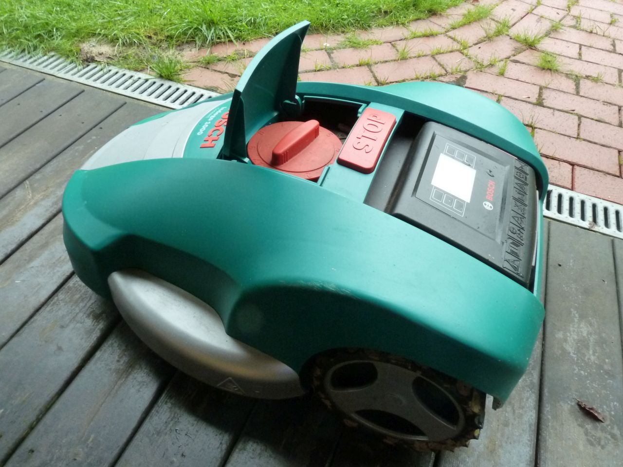
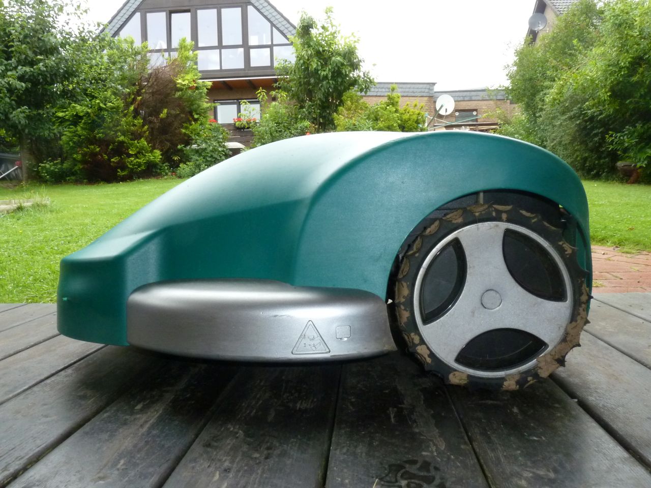
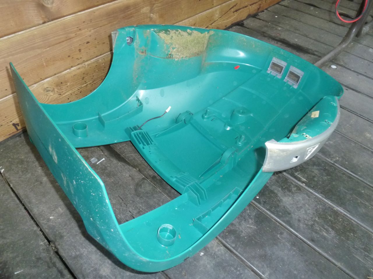
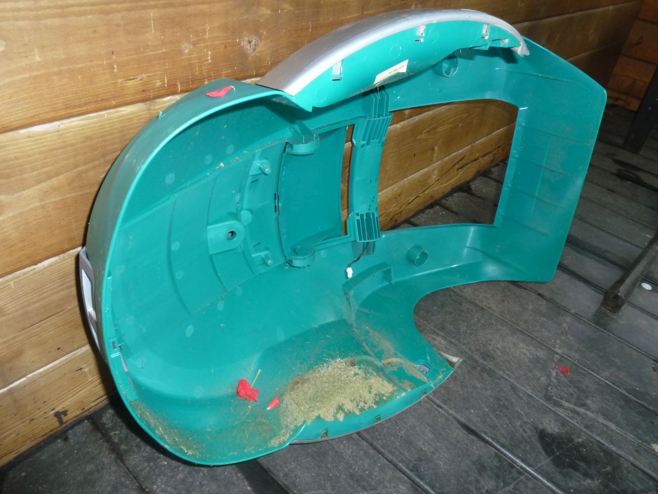
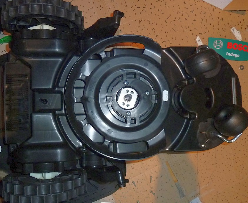
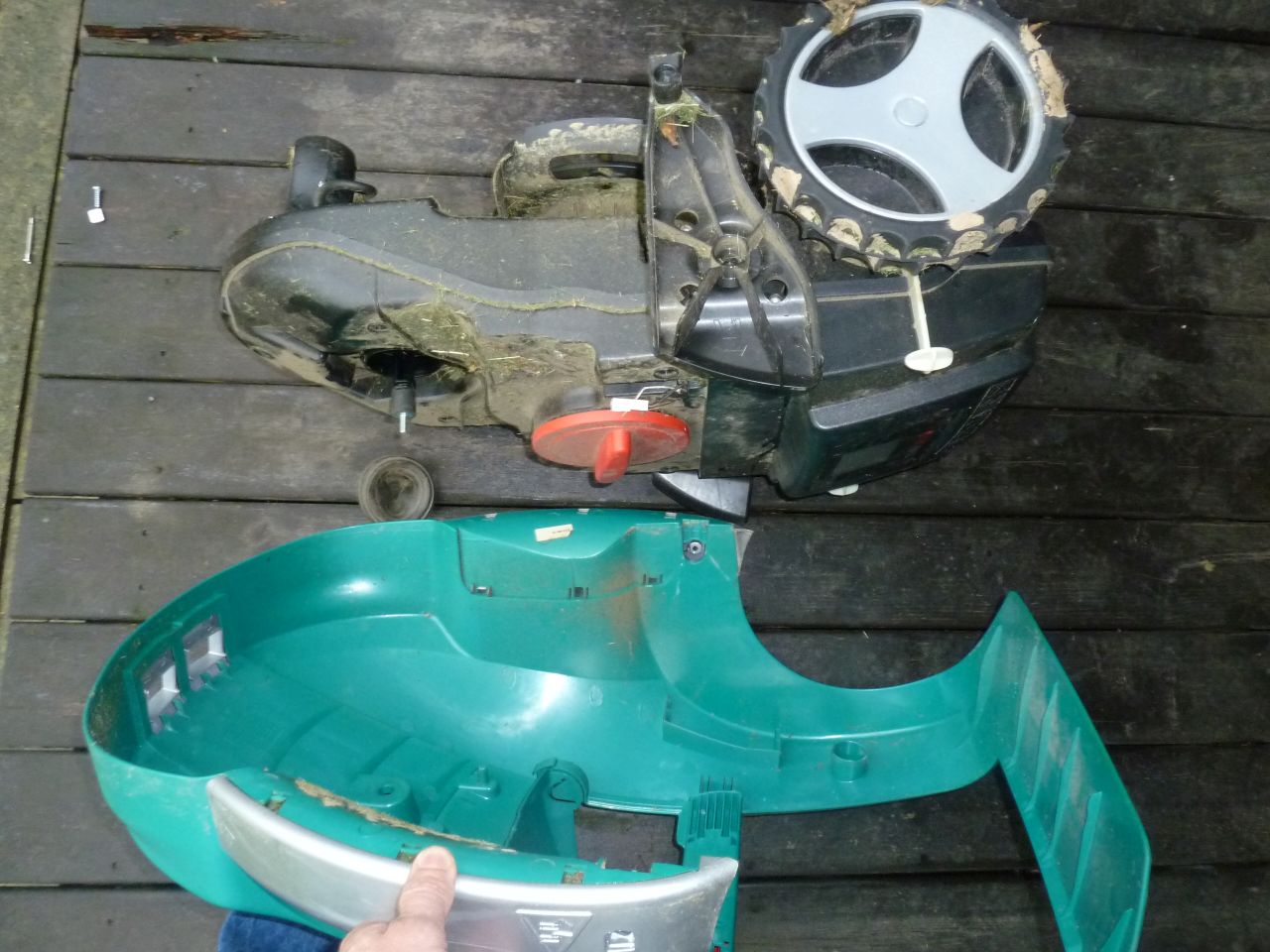
Cover
The cover (3.5 mm diameter) is mounted with rubber at 3 positions on the body (cover hanger is shown further below).
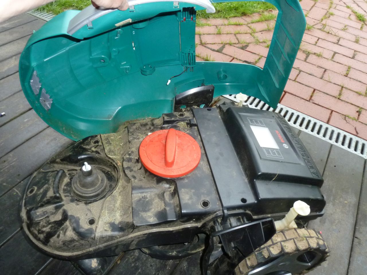
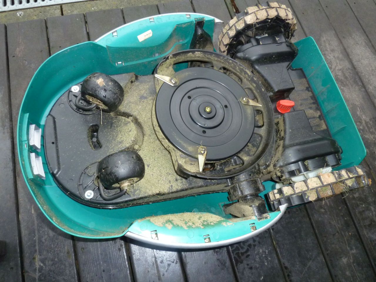
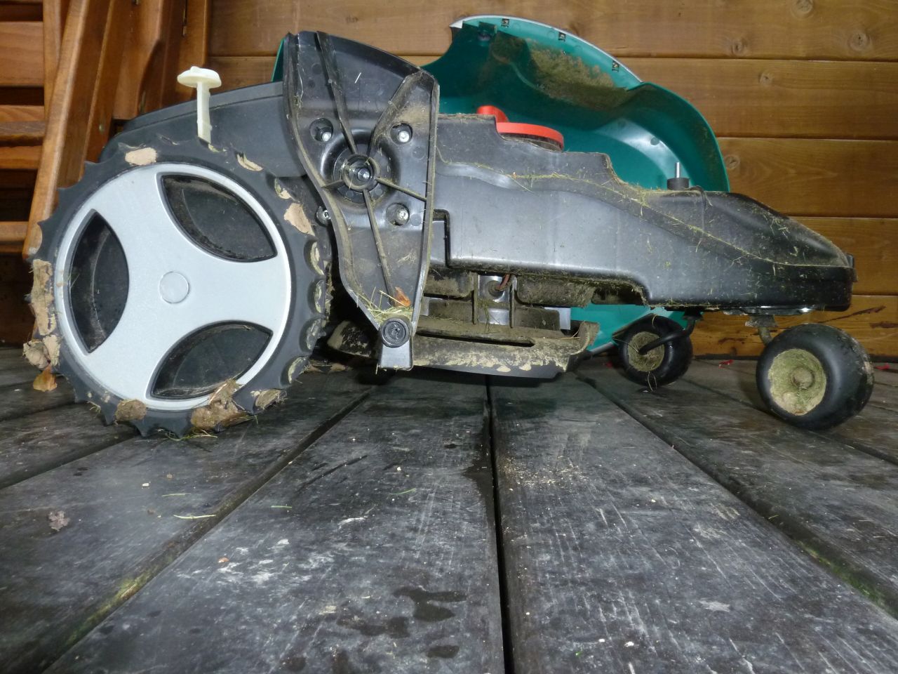
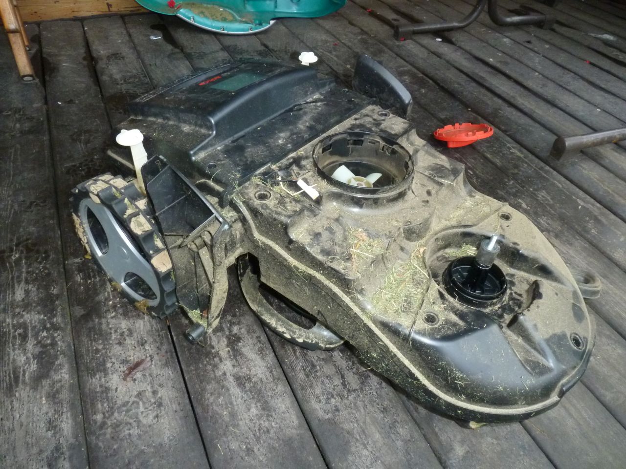
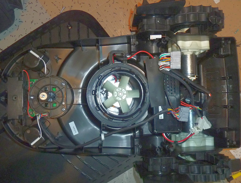
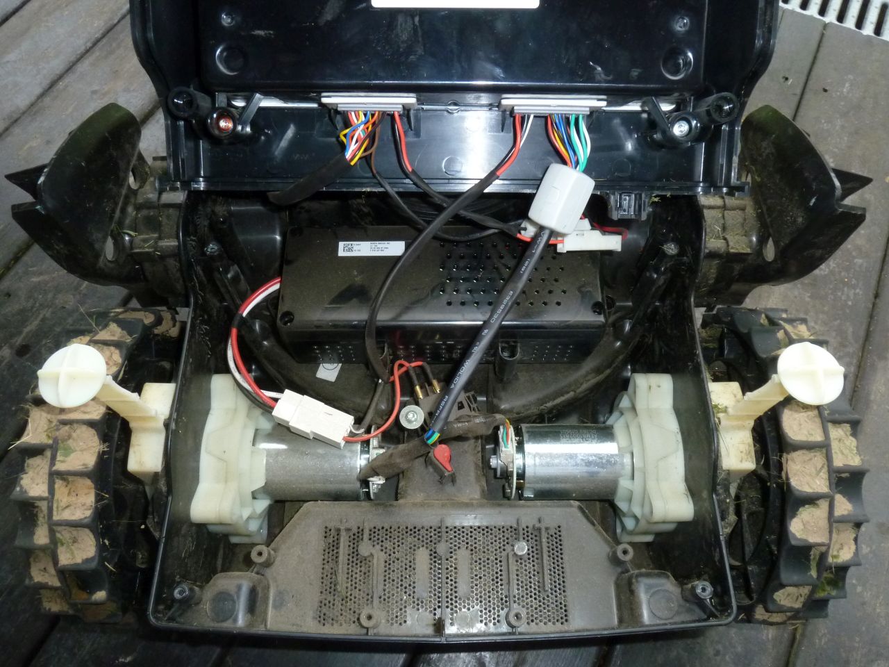
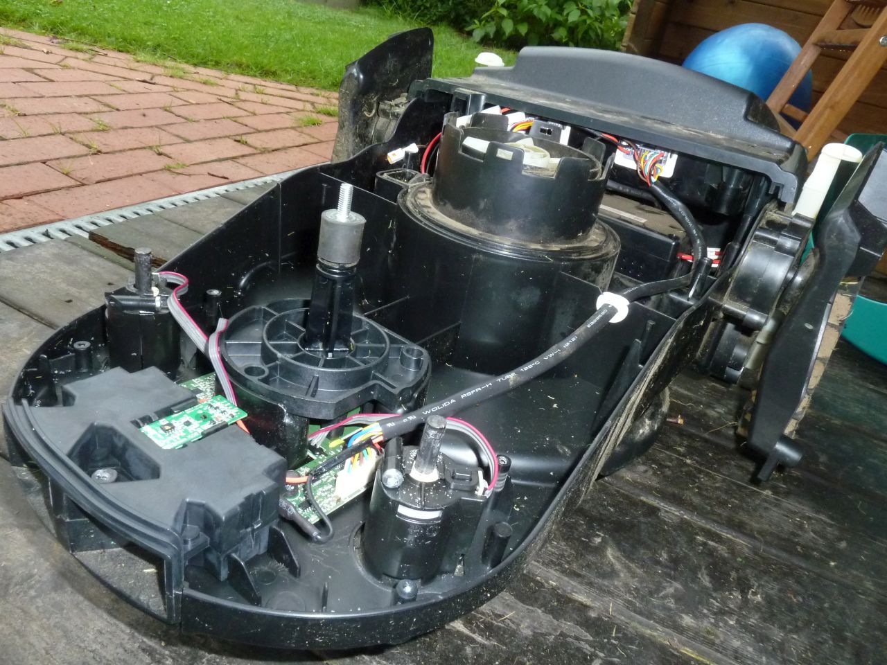
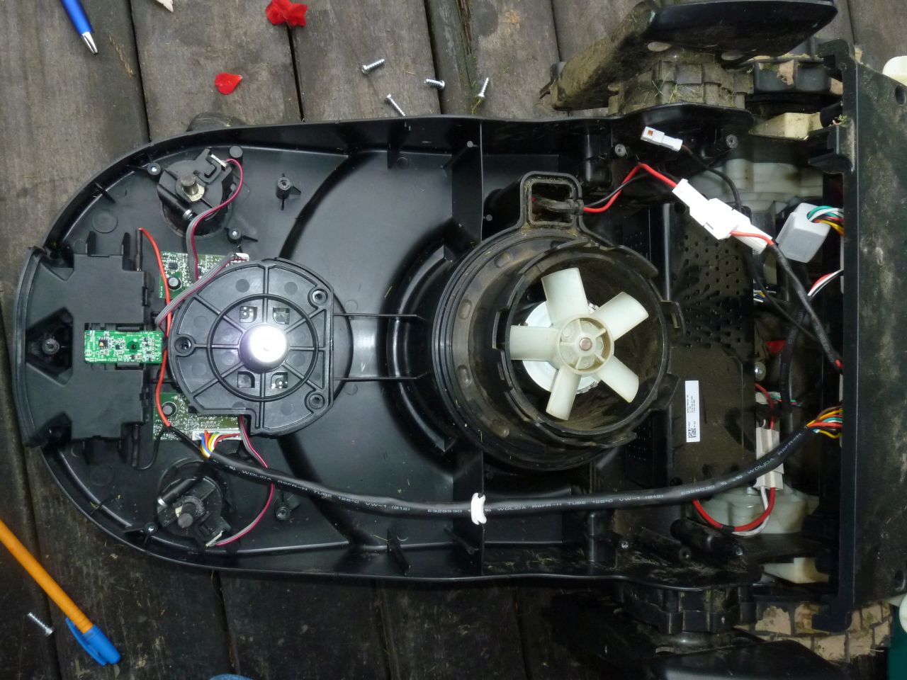
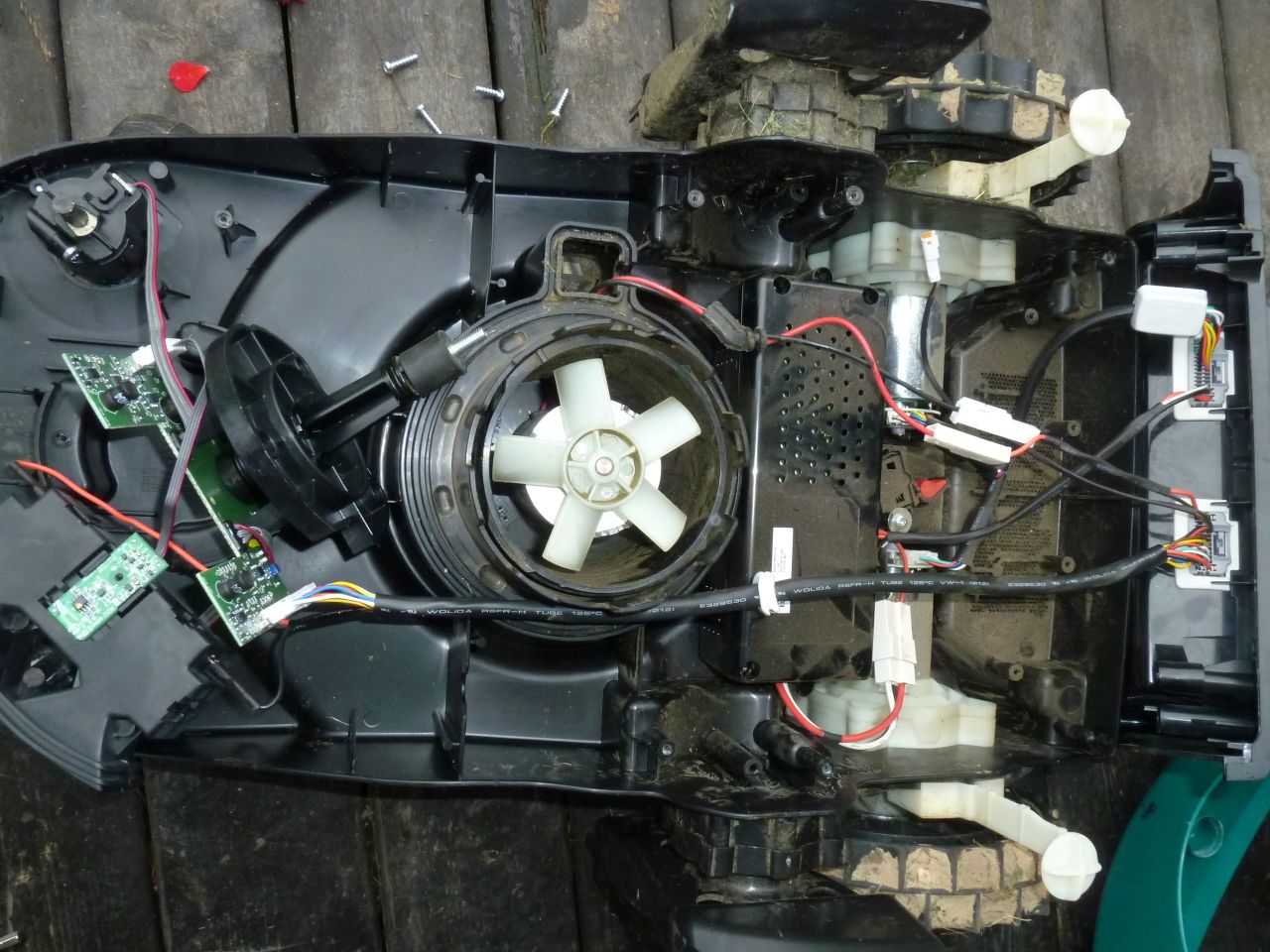
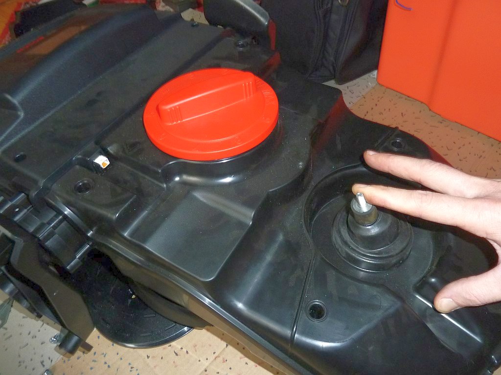
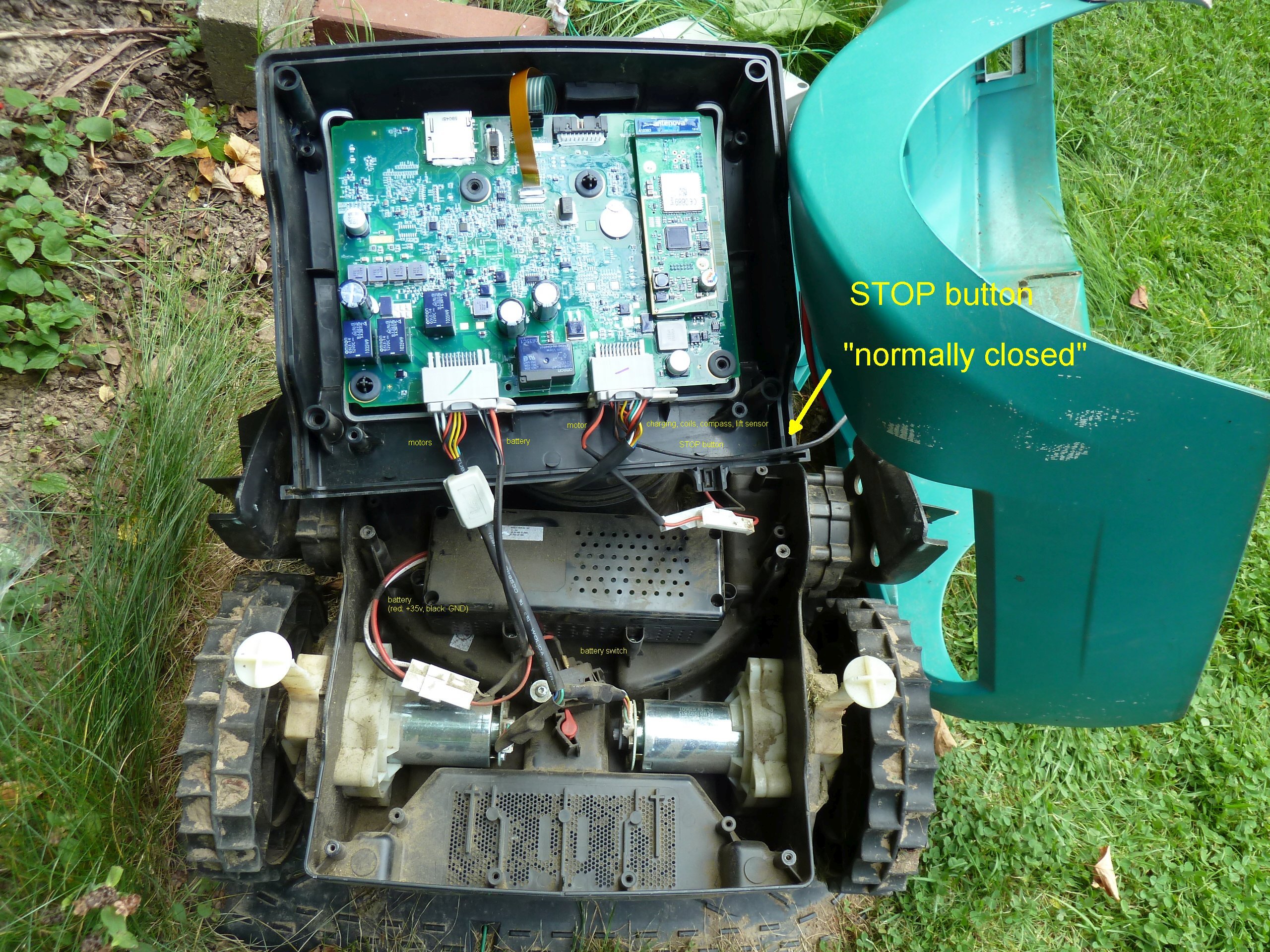
Body
From front to back: charging conacts, compass, perimeter receivers, mowing motor, battery, gear motors, battery switch

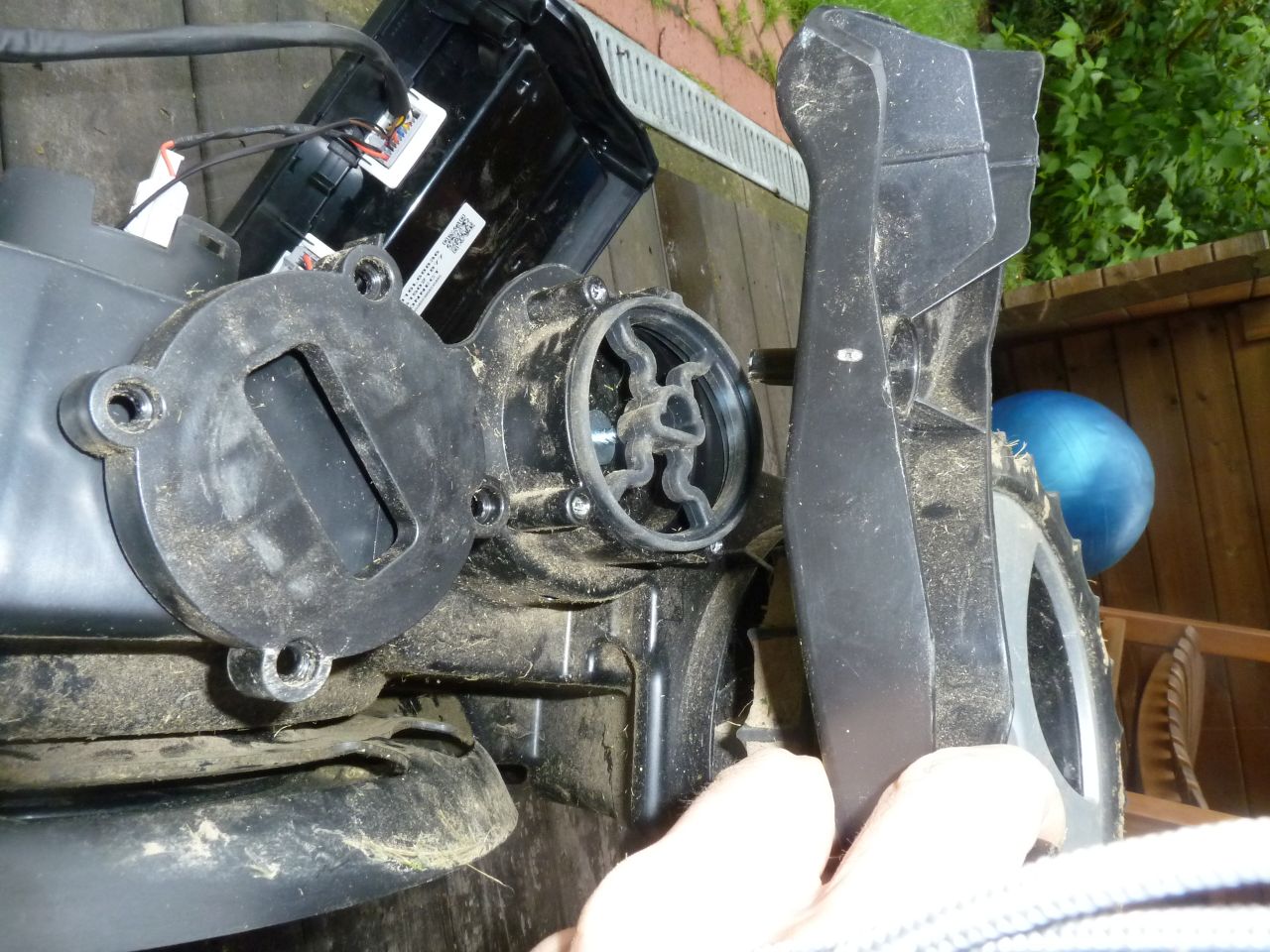
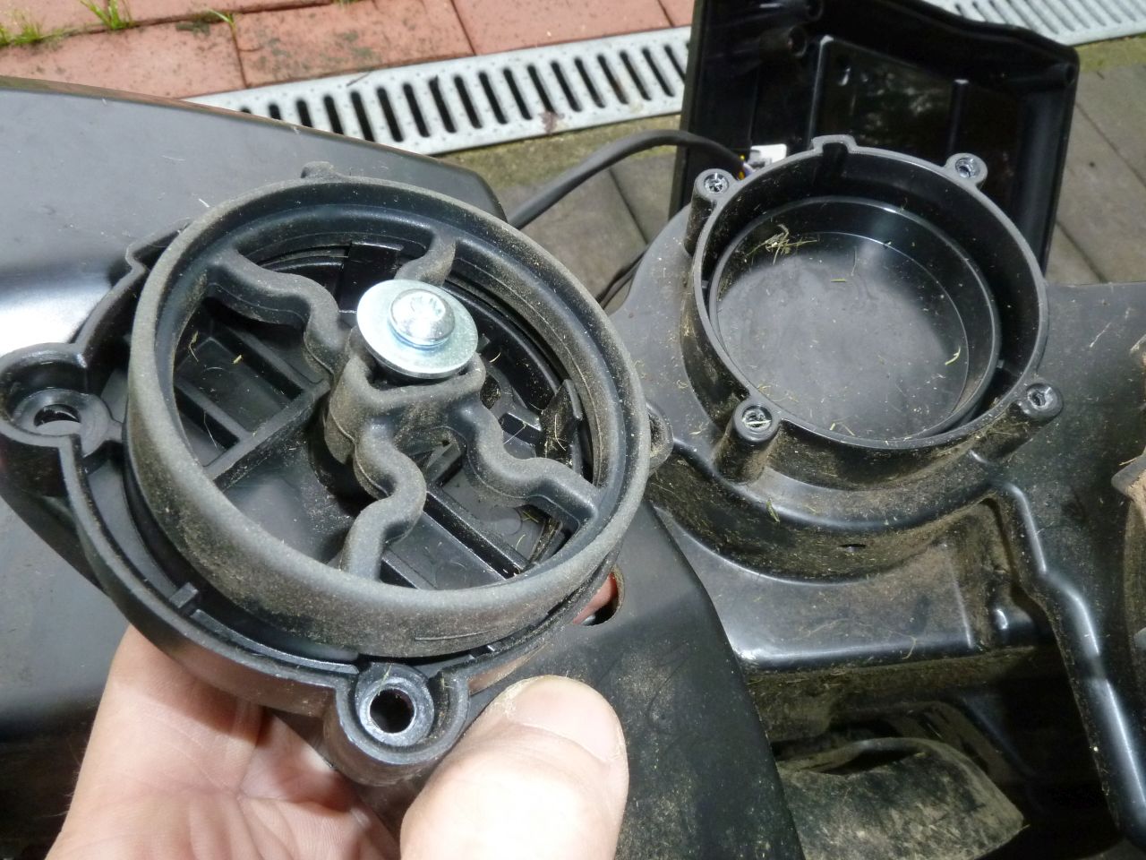
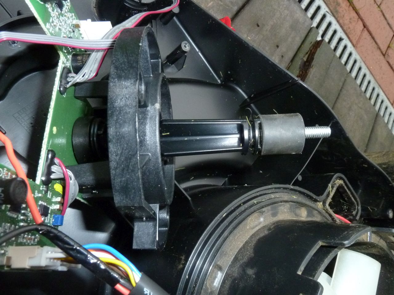
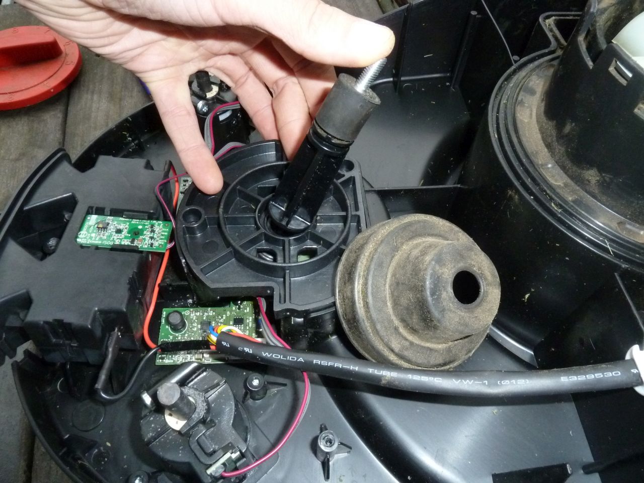
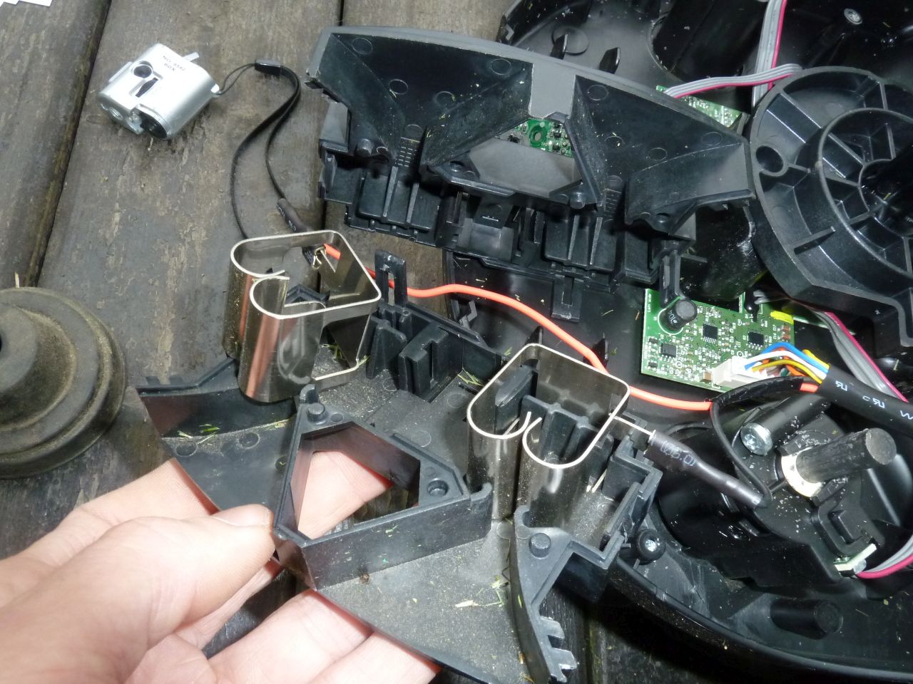
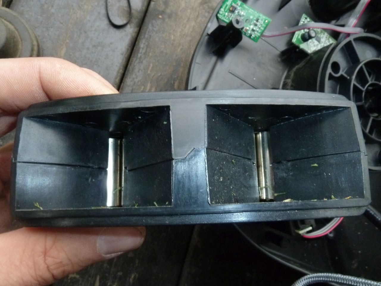
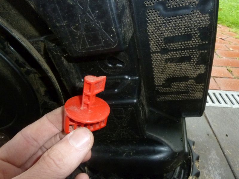
Cover hanger and bumper
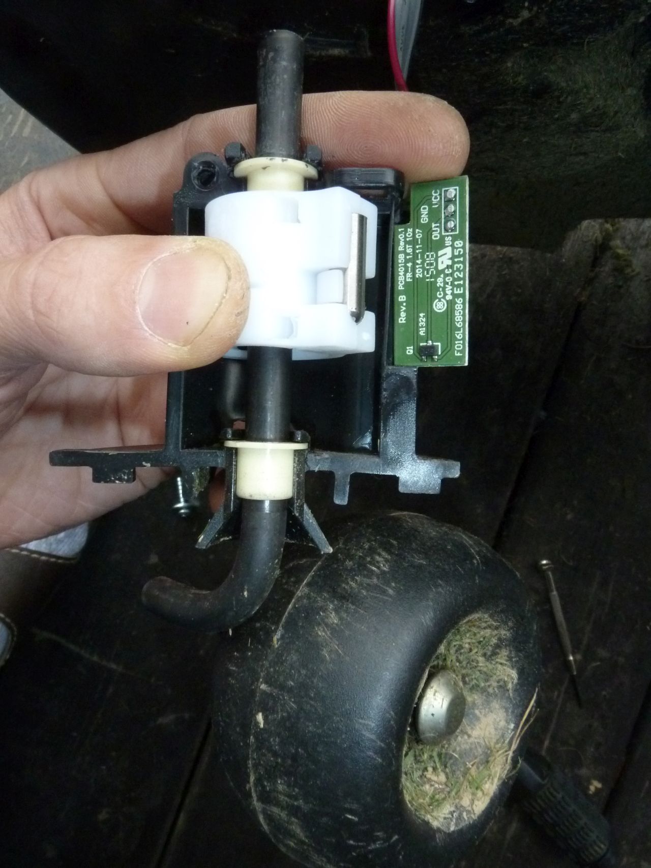
The cover is mounted with a rubber ‘joystick’ at 3 positions on the body. That way the cover works like an universal ‘bumper’ for the whole body. As soon as the Indego encounters an obstacle, the cover will move slightly (consume the impact energy), the motor current will increase, and the center ‘joystick’ will trigger one of the 4 hall effect sensors (north, west, east, south). I think they are linear hall effect sensor ICs with analog output. Possibly Allegro A1324. The IC’s have 324 written on them.
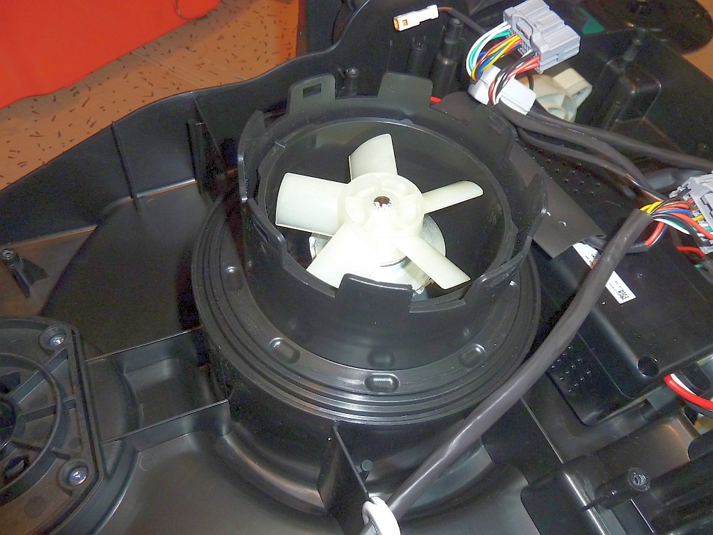
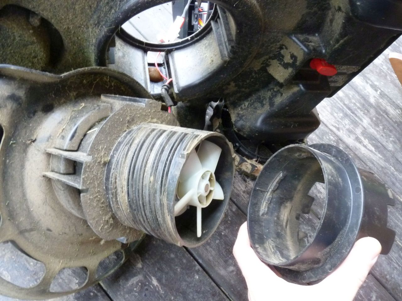
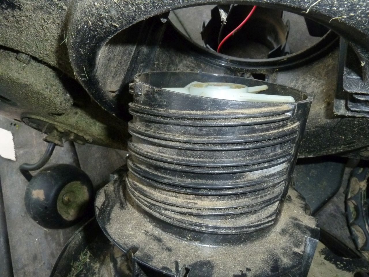
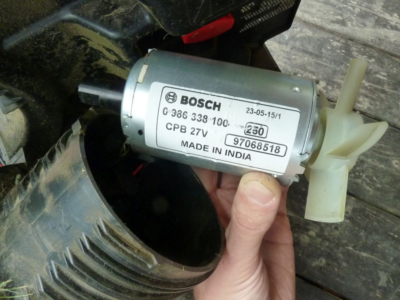
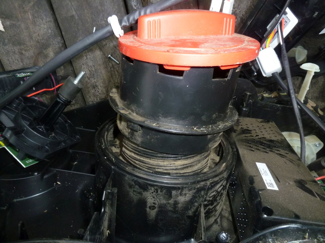
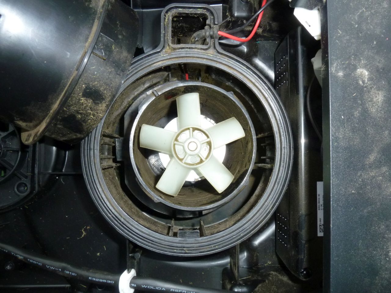
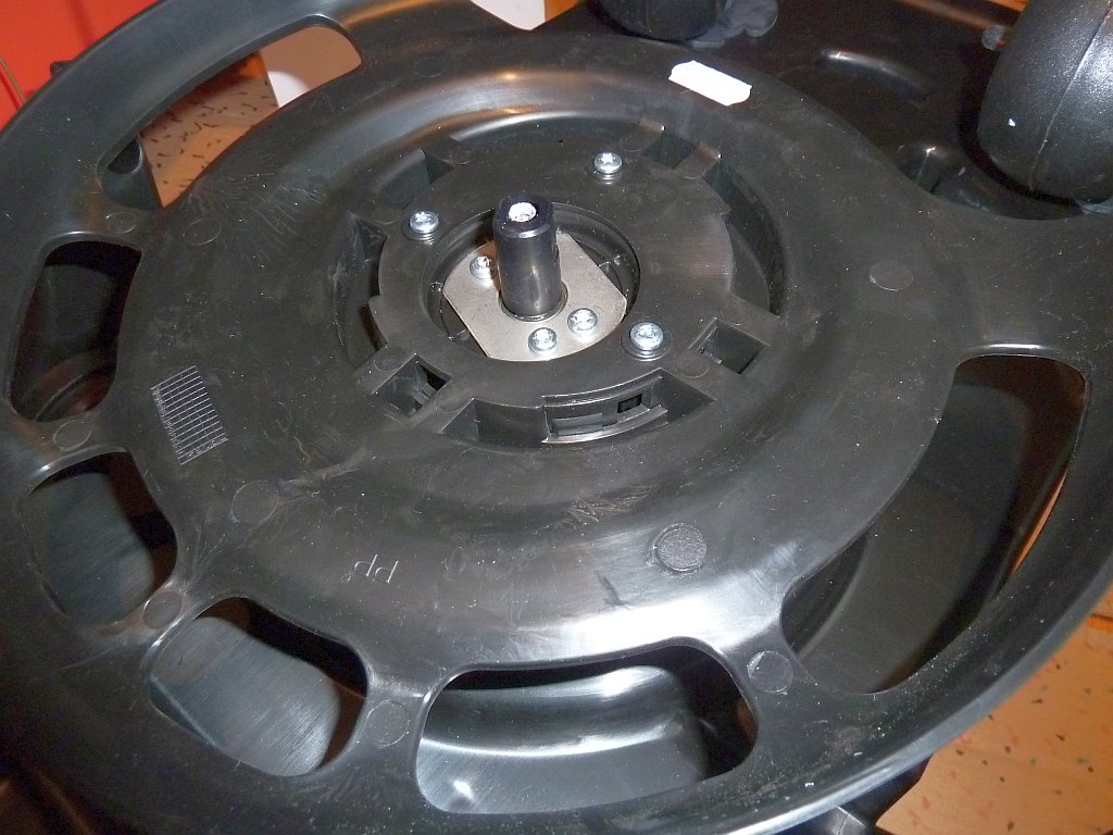
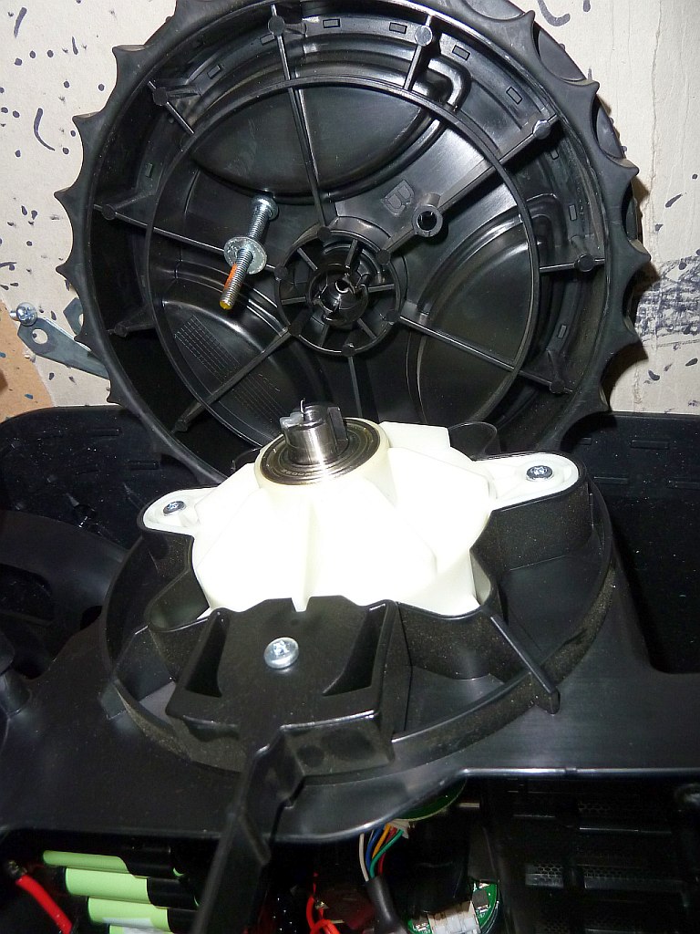
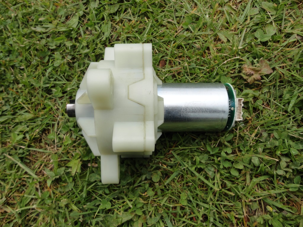
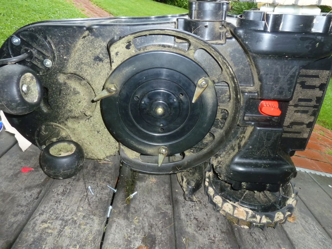
Mowing motor
The mowing motor can be lifted up/down, 24V, 87W, 5A, 3700 rpm, 22 Ncm
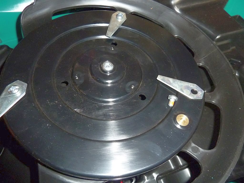
Blades

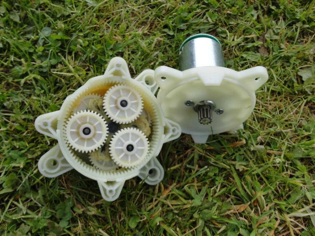
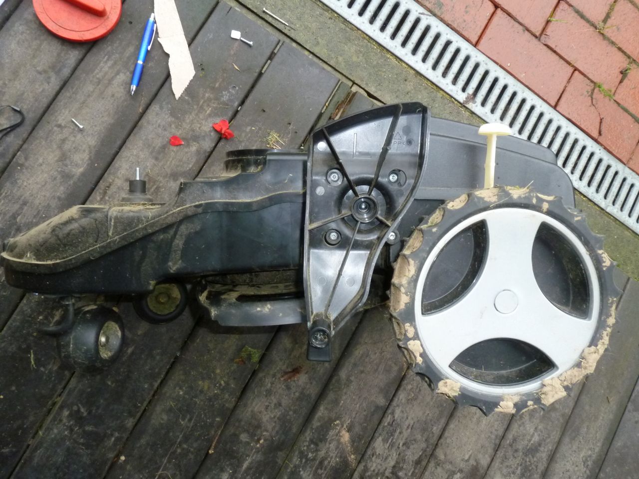
(photo source of last two drive and gear photos: http://www.roboter-forum.com/showthread.php?4384-Bosch-Indego/page80)
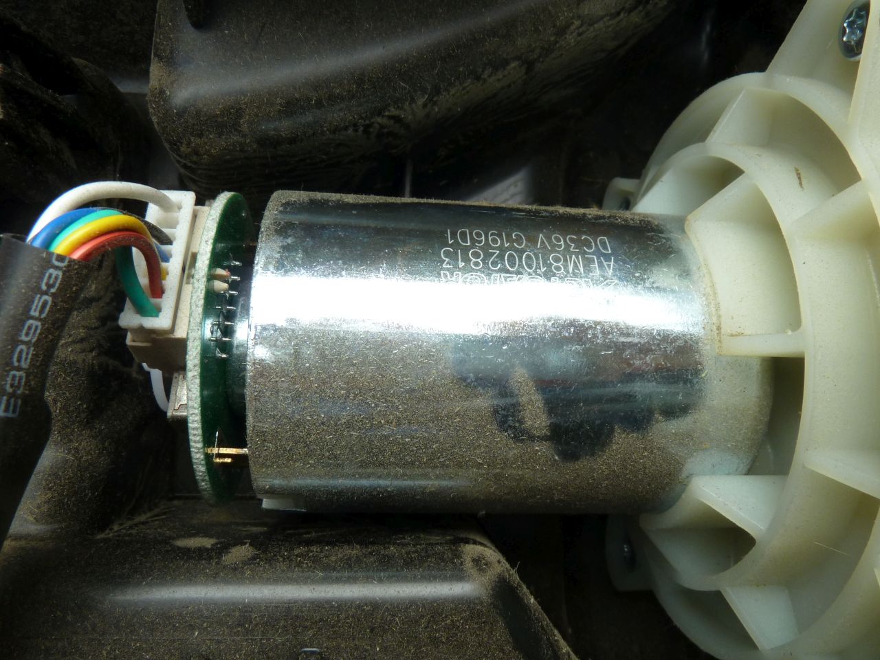
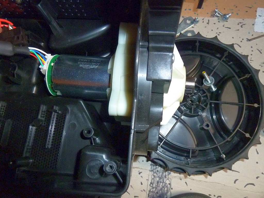
ACTUATOR AEM81002808, DC 36V, D383A2, estimated 30 Watt
ACTUATOR AEM81002813, DC 36V, G196D1
magnetic encoder
gear motor wiring (assumption): thick wires (white and green) for motor +/- and thin wires for encoder (red VCC, black GND, blue/yellow encoder signals)
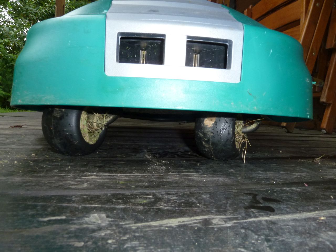
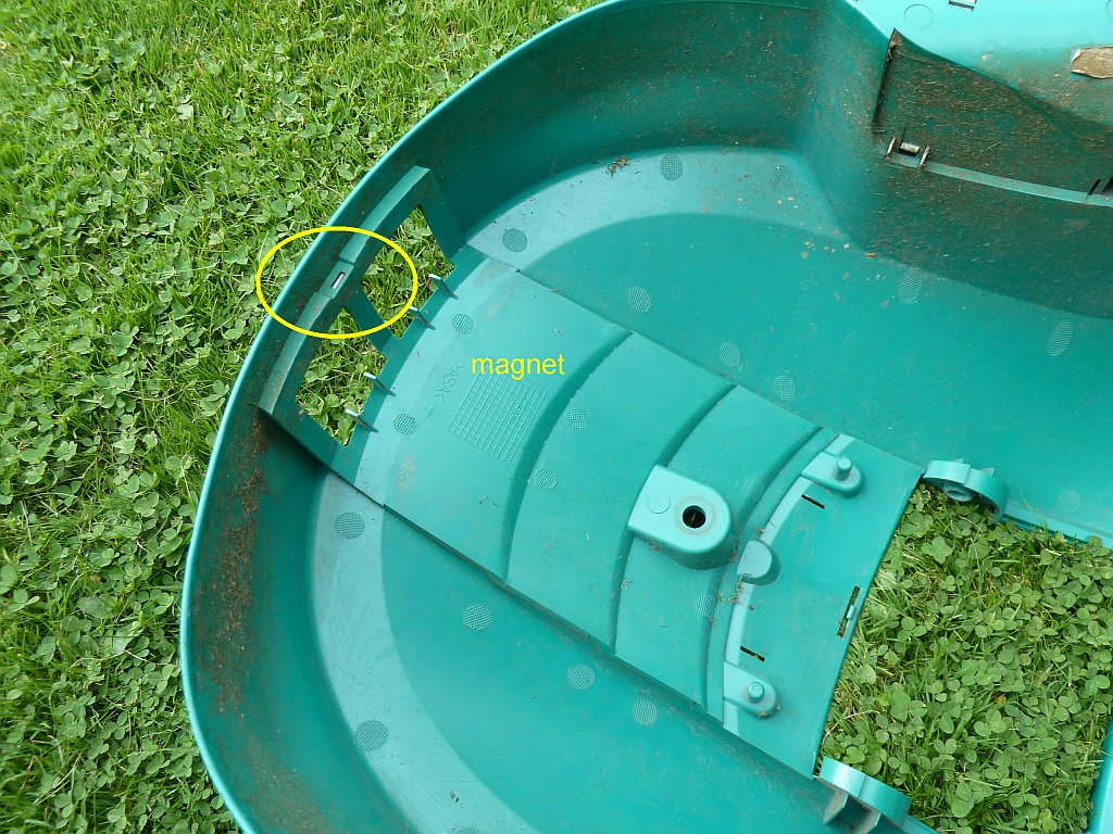
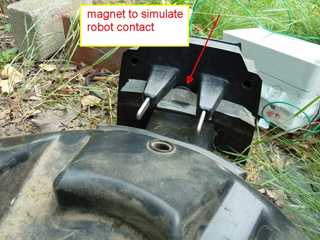
Charging contacts
Charging station
- Charging station generates DC voltage 4.8 V – Looking at robot front side, left side is (+) and right side is (-)
- Robot contacts charging station, DC voltage drops to 2.8 V
- This voltage drop (and the robot’s front magnet) is detected by charging station, and it generates 42 V for a few seconds
- These 42 V are detected by robot, and now you can turn on robot via display.
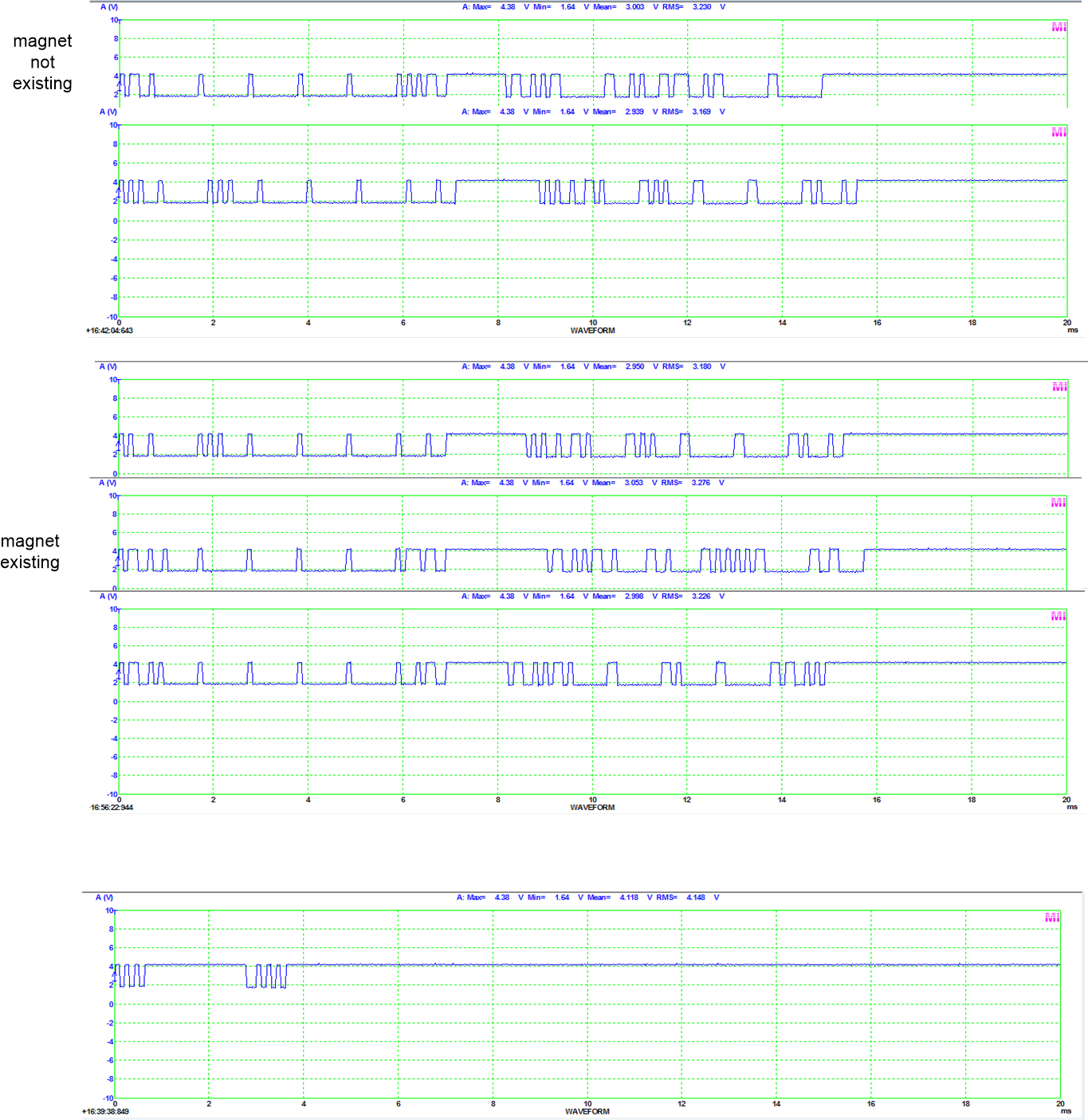
- Charging station sends “magnet OK” signal (HIGH=4.2V, LOW=1.8V) after turning off 42V.
Magnet OK signal as follows (LOW time microseconds, HIGH time microseconds):
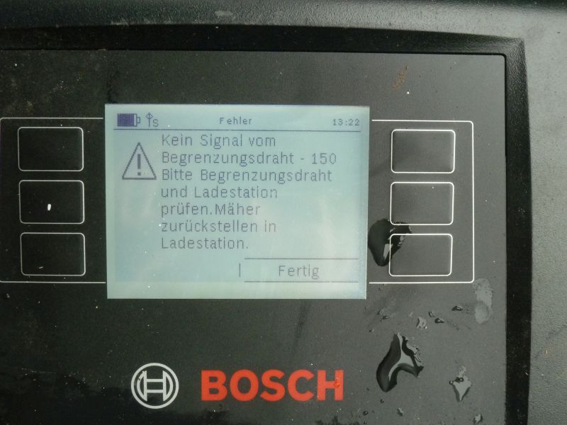
(12, 228), (168, 124), (64 , 124), (68 , 224), (172, 124), (588, 224), (172, 124), (592, 228), (68 , 124), (68 , 120), (68 , 124), (68 , 120), (64 , 228), (904, 224), (176, 224), (484, 53192) - As long as “magnet OK” signal is not sent, robot displays “perimeter error”.
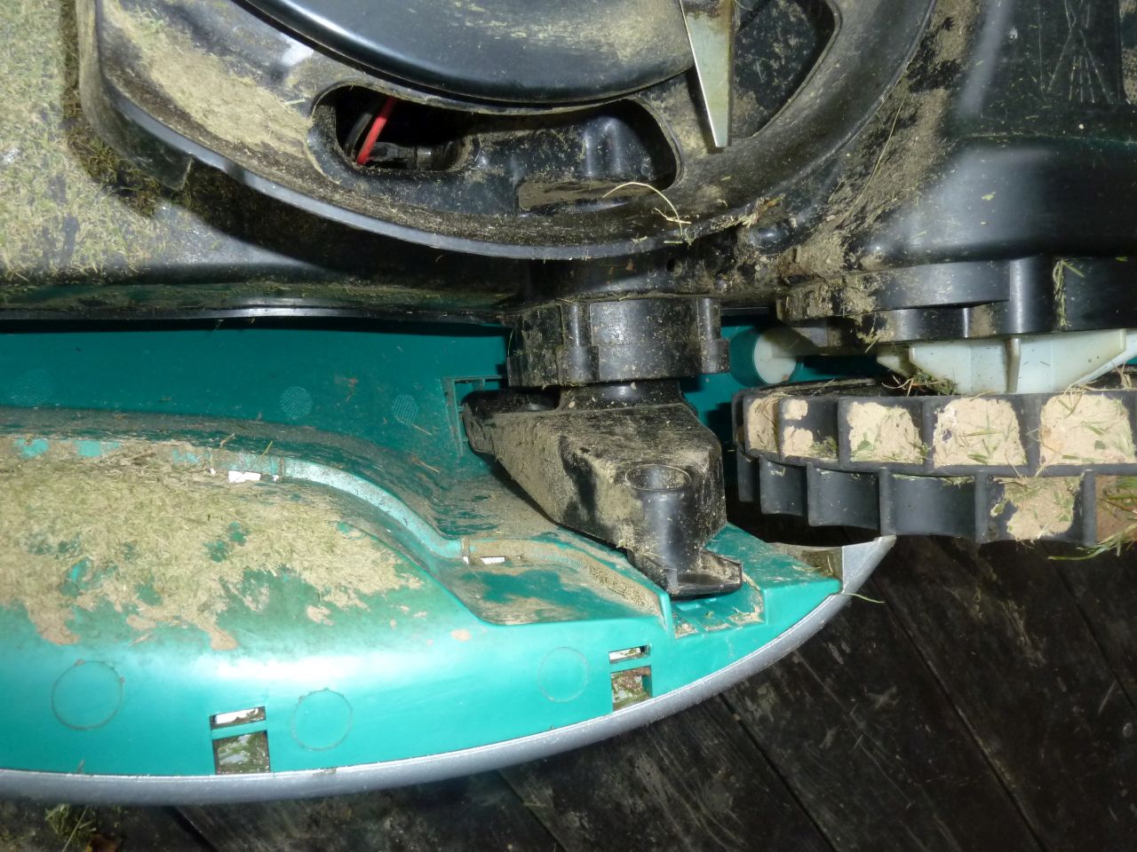
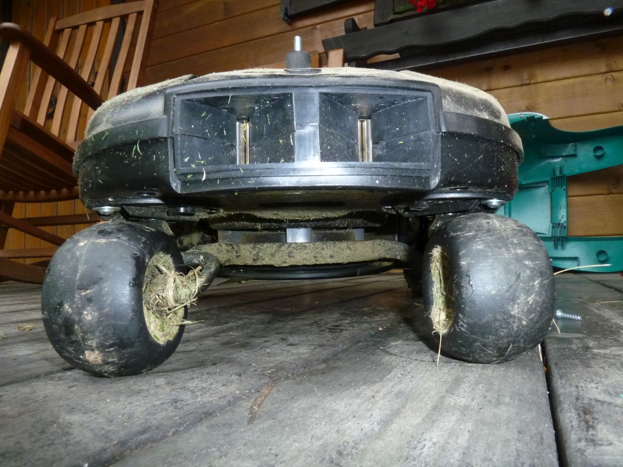
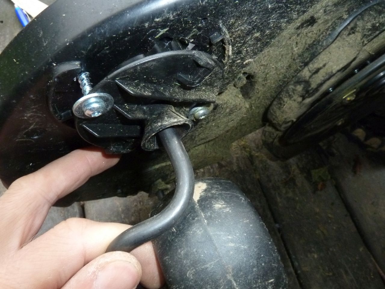
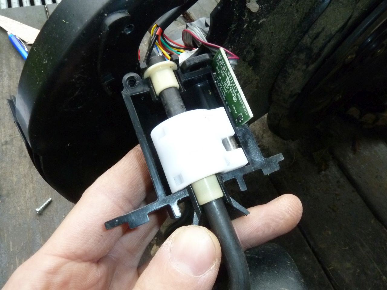
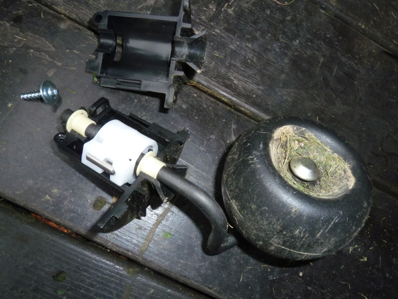
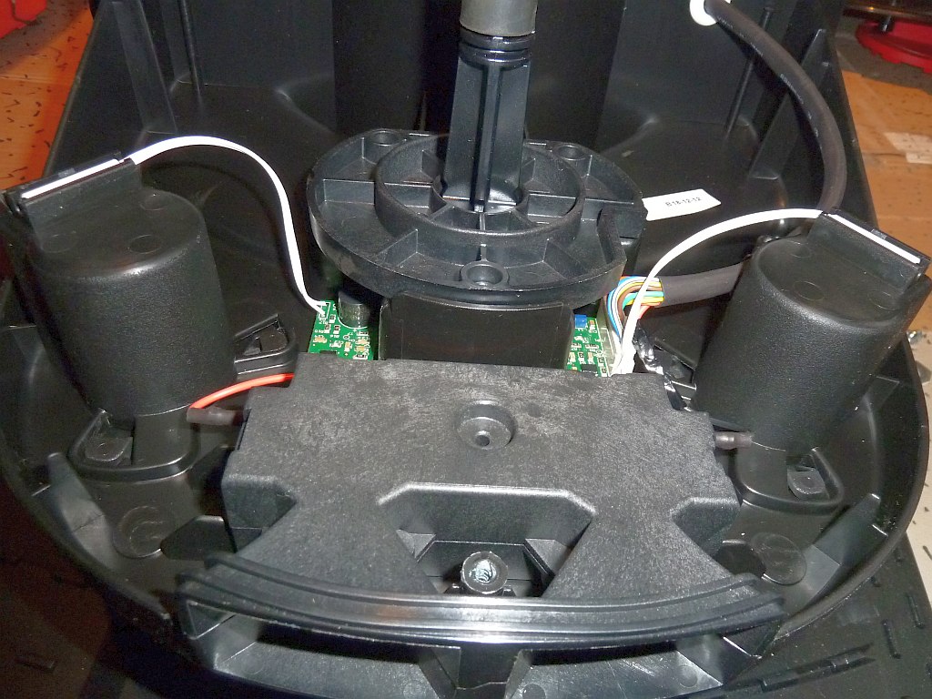
Free wheels
Hall sensors detect if the free wheels have ground…
LCD
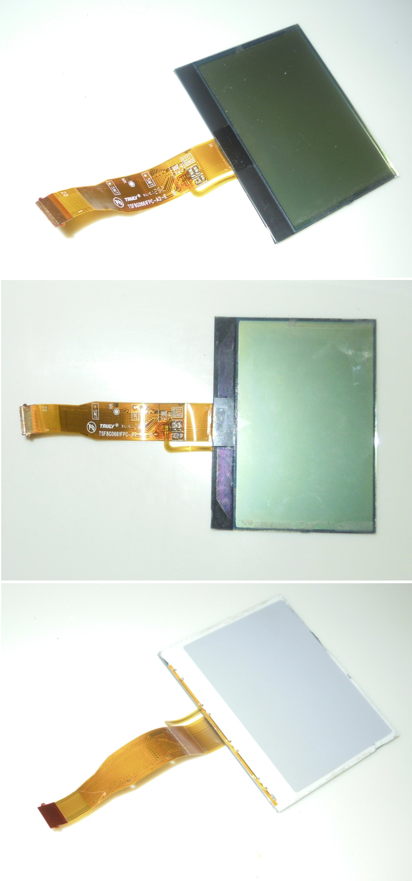
chip-on-glass (COG) module, 77mm x 61mm, 240×160 pixels, 35+2 pins at display, 20 pins at socket (0.5mm pitch, 10.5mm width), maybe based on ‘uc1698u’, maybe compatible to: Truly MG240160-1(ch) , RA8822S controller
(or ST7529, LH1560, LH1562 controller)
model numbers:
truly TSF 8G0661FPC-A2-E (Indego)
truly 8G1293FPC-A2-E (Indego Connect)
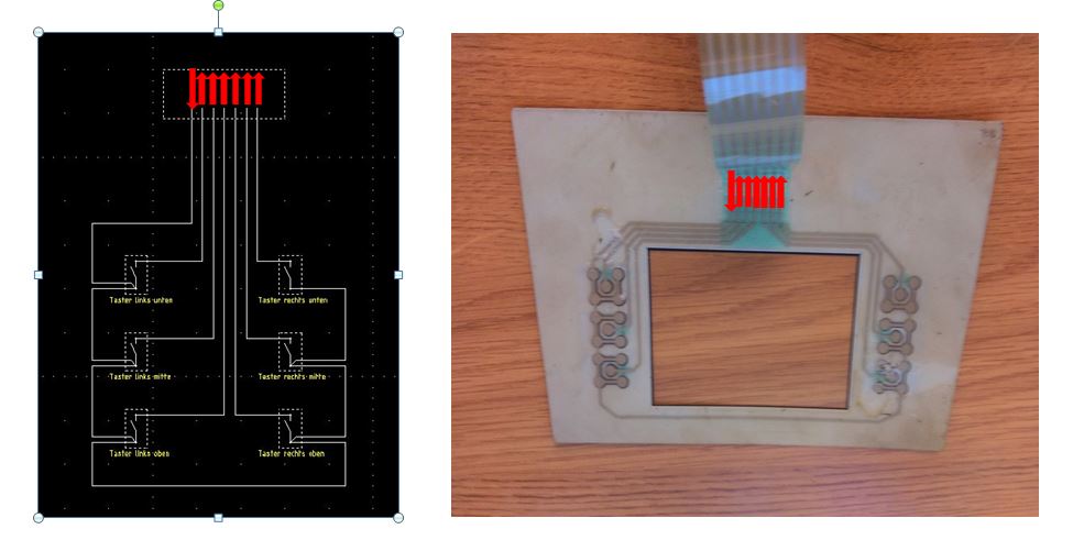
(Source of button photos: http://www.roboter-forum.com/showthread.php?17277-Bosch-Indego-Folientaster-defekt)
Wiring
Measurements
Power Standby (32V power, no 32V charge signal)
TP329, TP140, TP58: 32V
Power ON (32V power, 32V charge signal)
TP207, TP27, TP10, TP9: 32V
TP269, TP105, TP7: 12V
TP320, TP215: 6V
TP328, TP327, TP311, TP298, TP224, TP127, TP2: 5V
TP304, TP248, TP246, TP243, TP238, TP237, TP219, TP184, TP183, TP68, TP41: 3.3V
TP230: 2.8V
TP178, TP126: 2.5V
TP206: 1.8V
TP325, TP56, TP55, TP42, TP11: 1V
Power ON (32V power, no 32V charge signal)
TP27: 5V (charger data signal)
Regulators
Q17: 12V
Q3: 3.3V
Q29: 2.5V
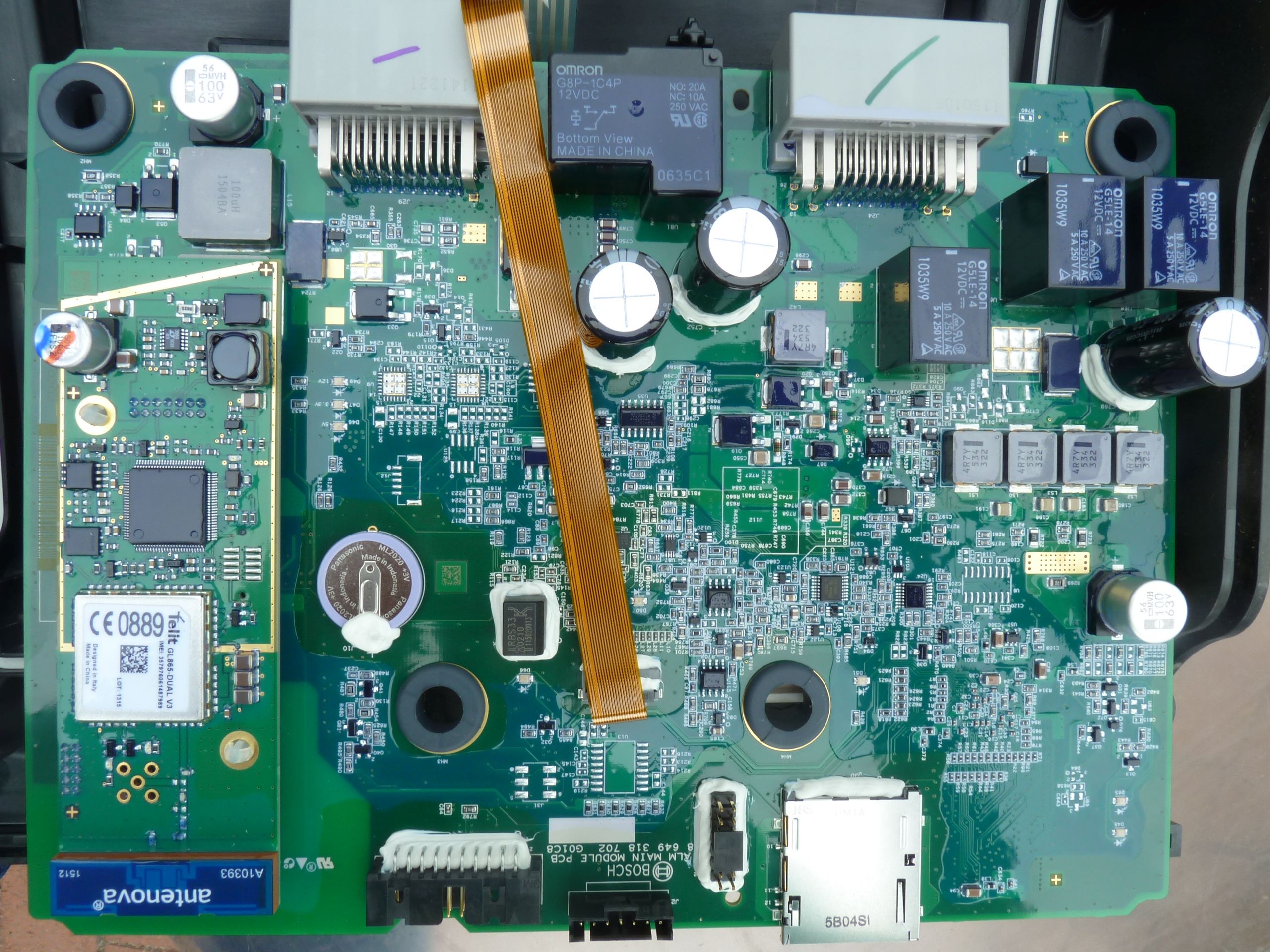
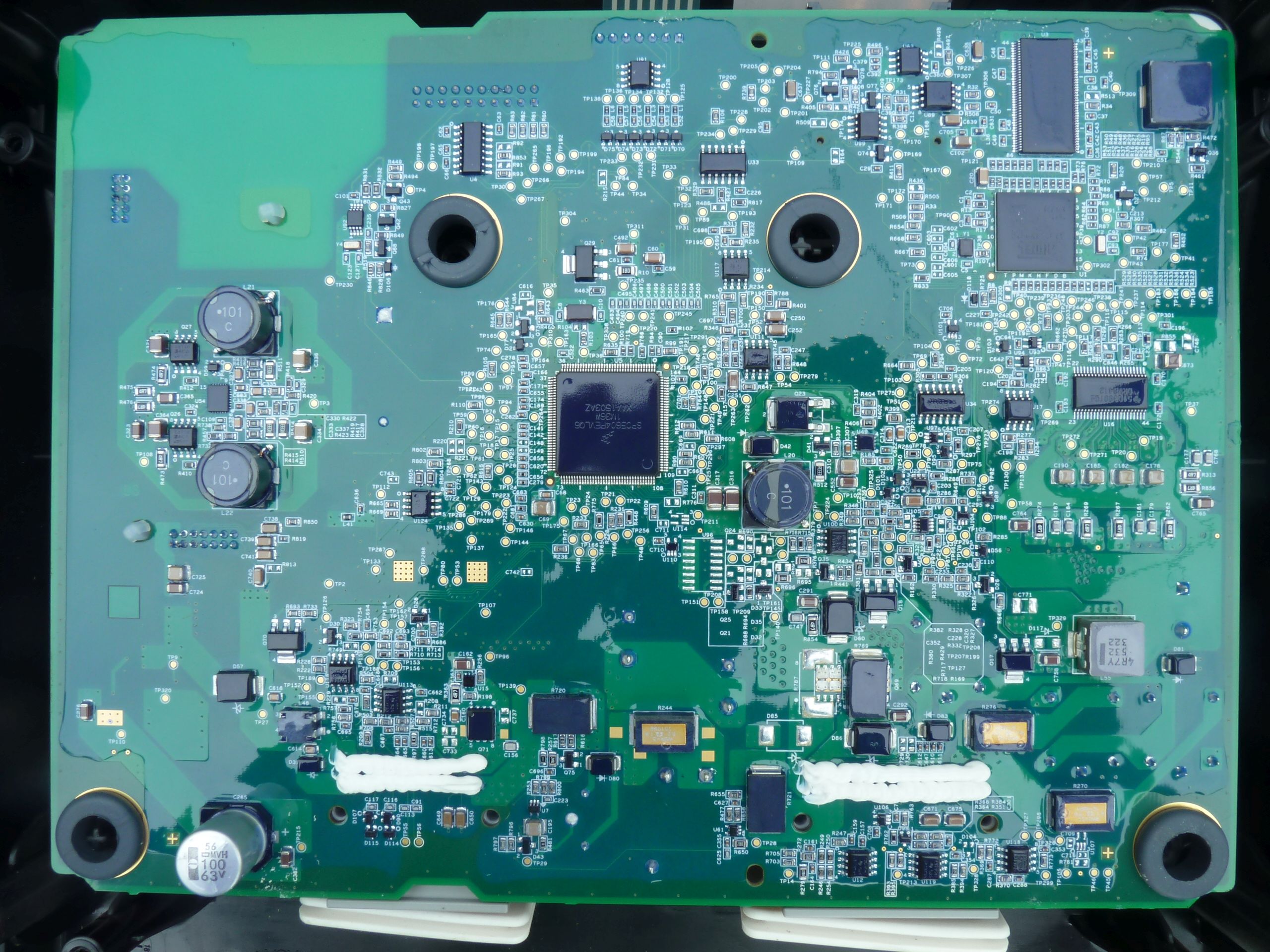
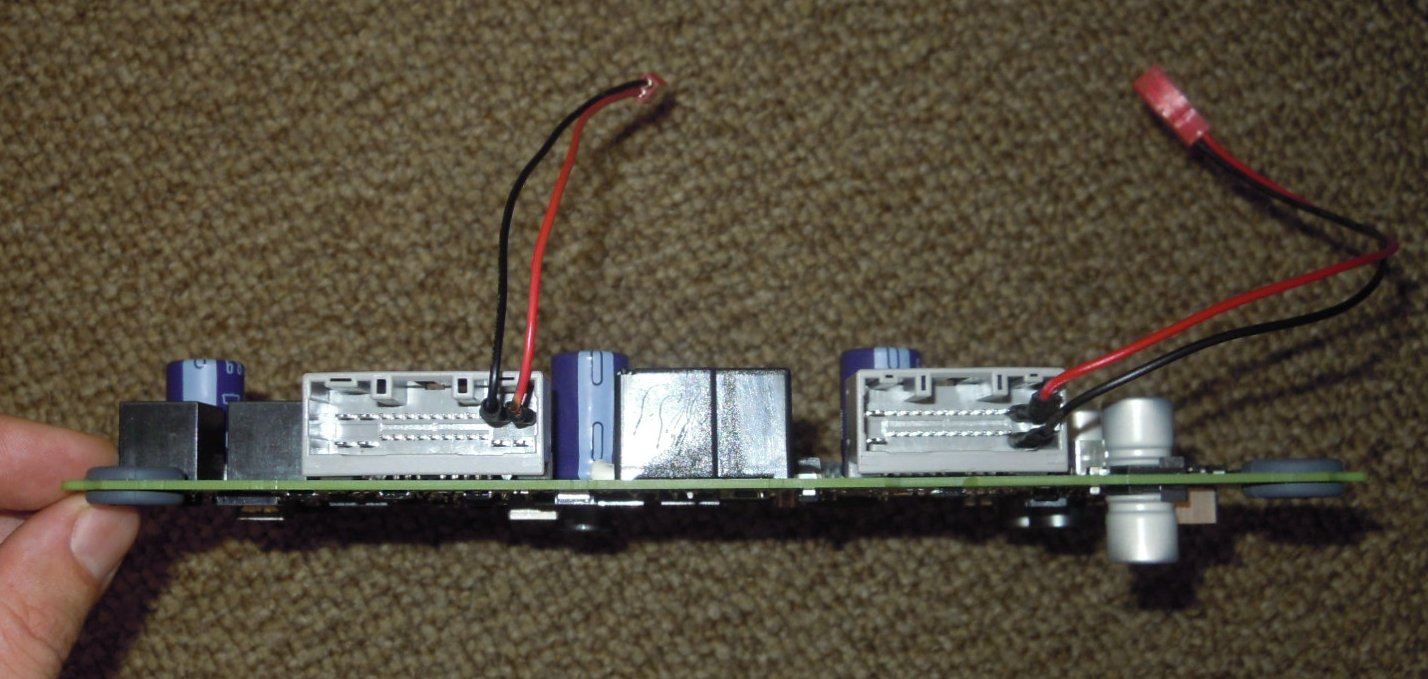
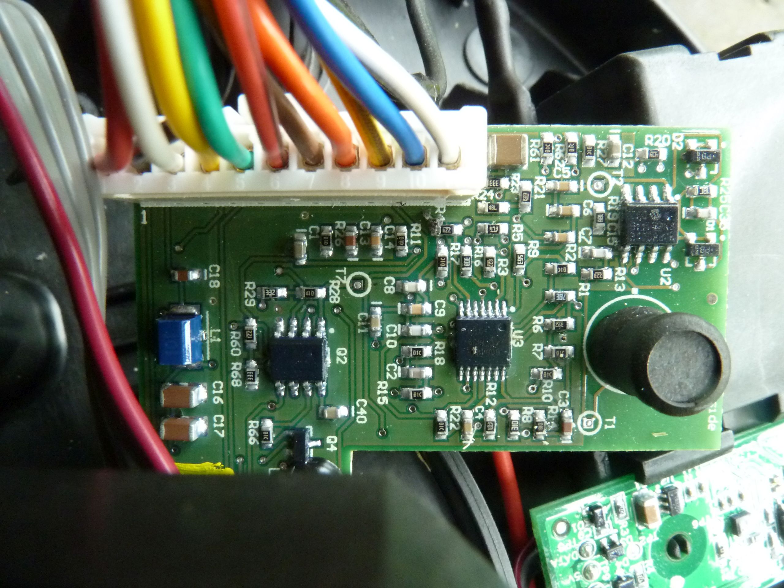
Mainboard
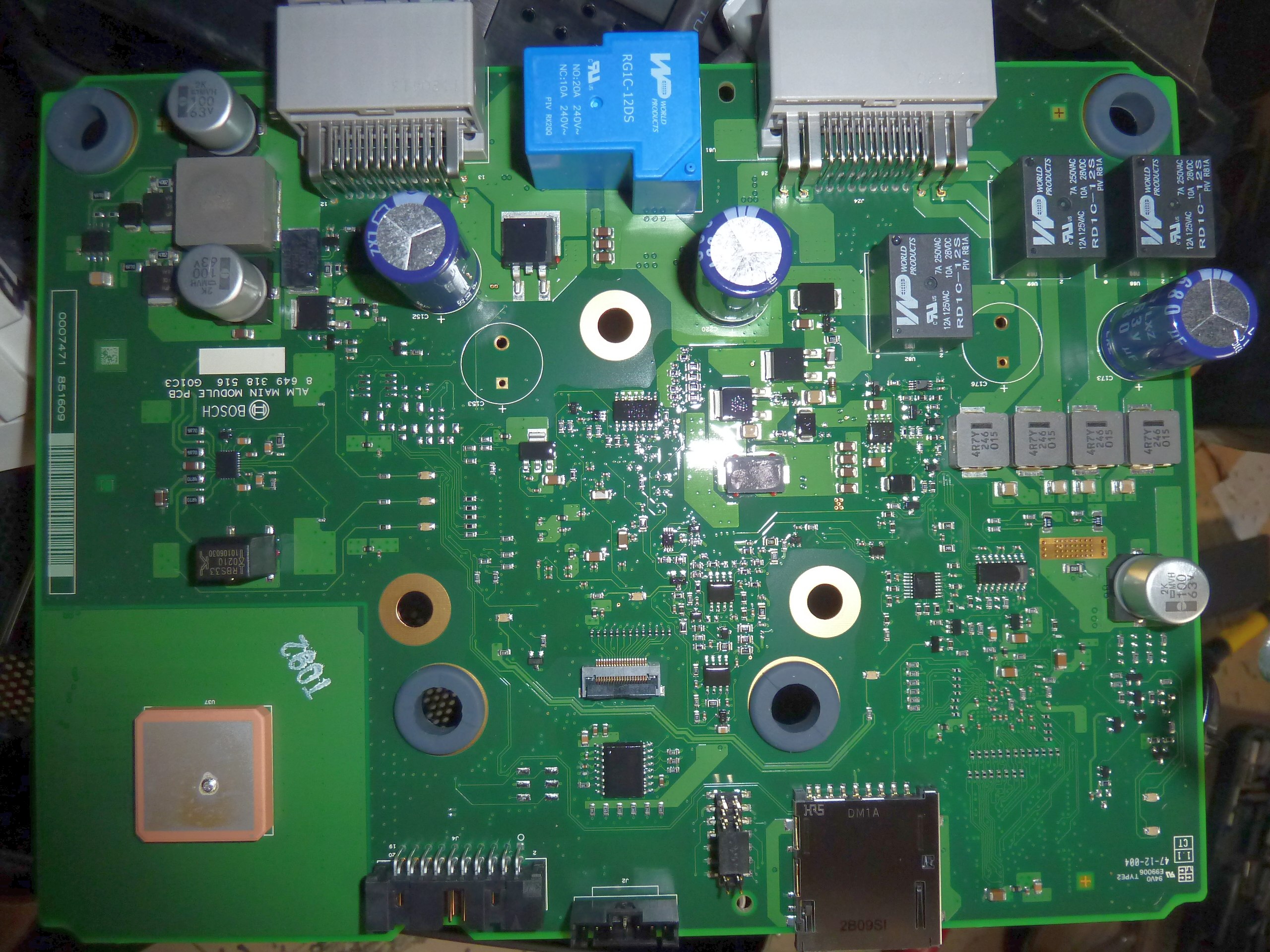
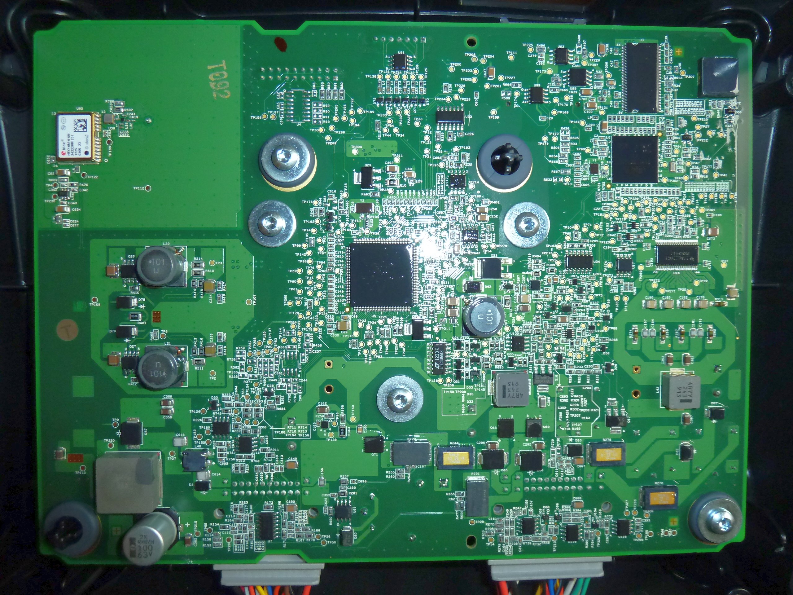
BOSCH ALM MAIN MODULE PCB 8 649 318 516 G01C3:
indego_pcb_top.jpg indego_pcb_bottom.jpg
Connect
BOSCH ALM MAIN MODULE PCB 8 649 318 702 G01C8:
How to run Mainboard on your desk
Connect 30V to power pins, then connect 30V to charge pins for at least 1 second and board will start.
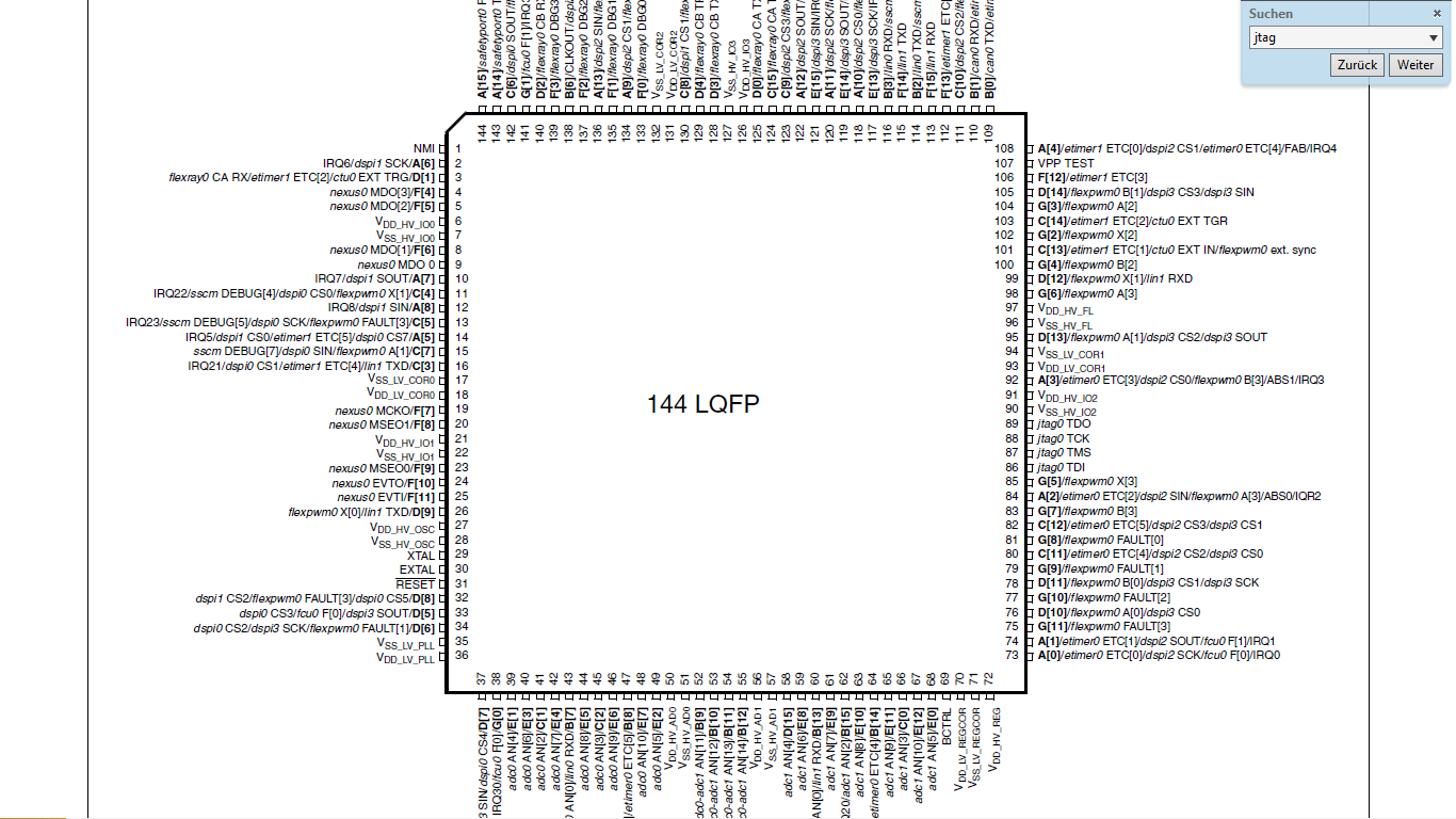
JTAG Connector
(JTAG + Nexus/IEEE-ISTO 5001-2003)
location: near SD card reader, pin1 points to board center
MPC5604P IDCODE: 0x5ae2101d [0101 1010111000100001 00000001110 1]
  TDI--7 8 --GND
  TDO--6 9 --GND
  TCK--5 10--GND
 EVTI--4 11--NC
RESET--3 12--TMS
  VDD--2 13--GND
   NC--1 14--JCOMP
Arduino code (setting debug bit not working/incomplete): jtagduino
More details in robotic forum: http://www.roboter-forum.com/showthread.php?17511-Indego-am-Schreibtisch-auslesen
Serial connector
MAX232 only found in connect, Pin1 at right bottom
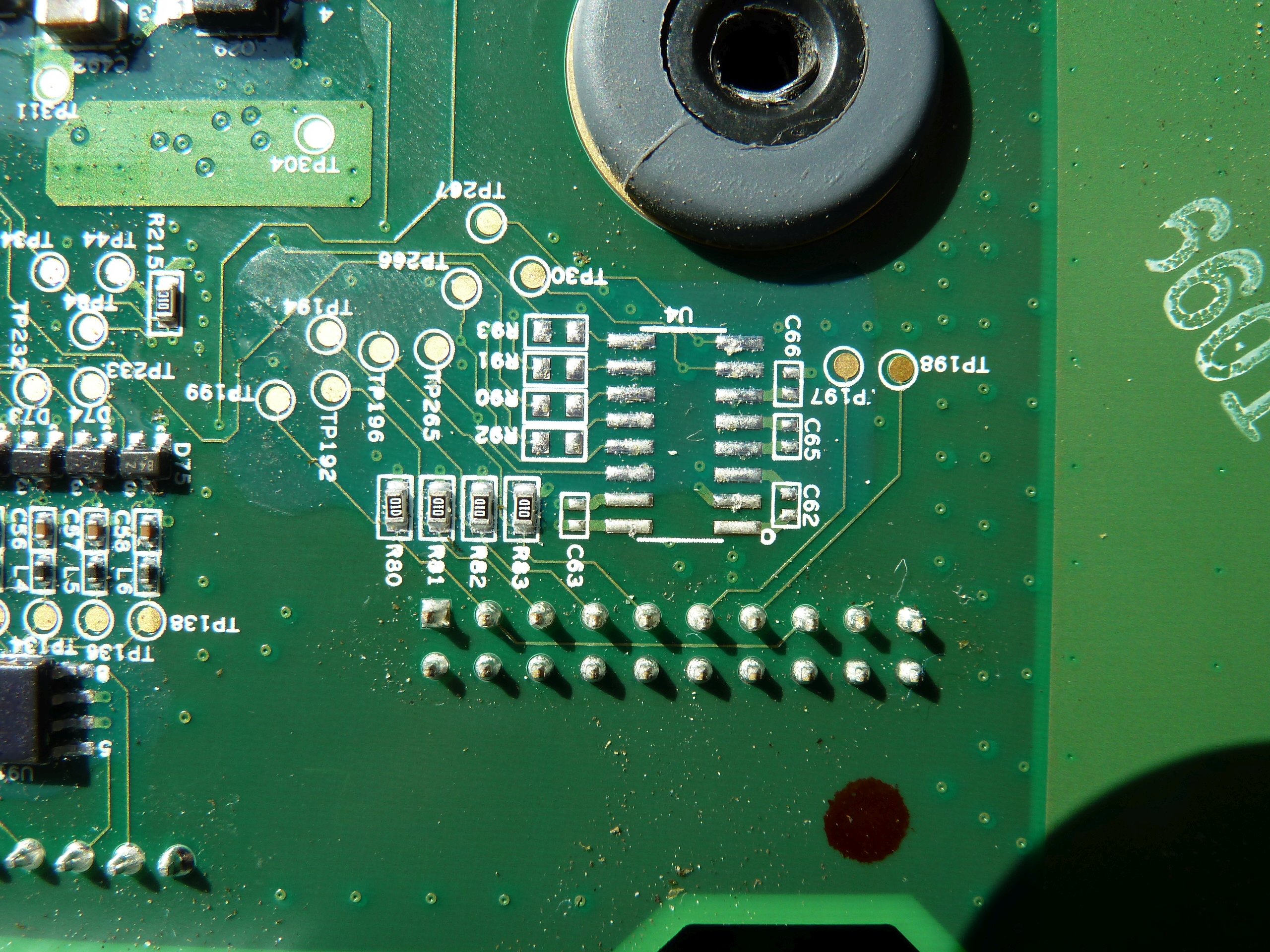
VCC--10  11--TP304
 GND--9  12--TP199
 GND--8  13--R81
 GND--7  14--R82
 GND--6  15--TP196
 GND--5  16--TP197
 GND--4  17--TP198
 GND--3  18--12
 GND--2  19
 GND--1  20
@CPU:
TXD (pin 114) — TP263
RXD (pin 116) — TP296
another serial communication on TP181, TP182, TP240, TP242, TP243?
ICs
Bosch 4254X P1235 16 Pins
Linear 2E 3850 B2606 30 Pins (Step-down Converter)
74AHC30D (NAND)
MV3581 (OPAMP)
LV123A (Monostable Multivibrator)
U16: DRV8412
U17: IT OPA 2376 (Low Noise OPAMP)
U99: 5V0L6US (diode array)
U89: ATMEL1116 (EEPROM)
U63: 2049
U33, U34: 74HC30D (NAND)
U111, U113, U116, U117: MV3581 (OPAMP)
U91: NXP 5V0L6US (diode array)
U7: 16TESM
Q71: 028N06LS HAB231 (power transistor)
U61: TI OPA 2376 (OPAMP)
U96: LTC4355IS (diode OR)
MAX23221
CPU
Freescale SPC5604PEVLQ6 (MPC5604P), 64MHz, 32 Bit, 512 KB Flash, PowerPC RISC (robot control)
Mikrocontroller AT91SAM9G10, ARM, 266 MHz, 96 I/O Pins (display, menu)
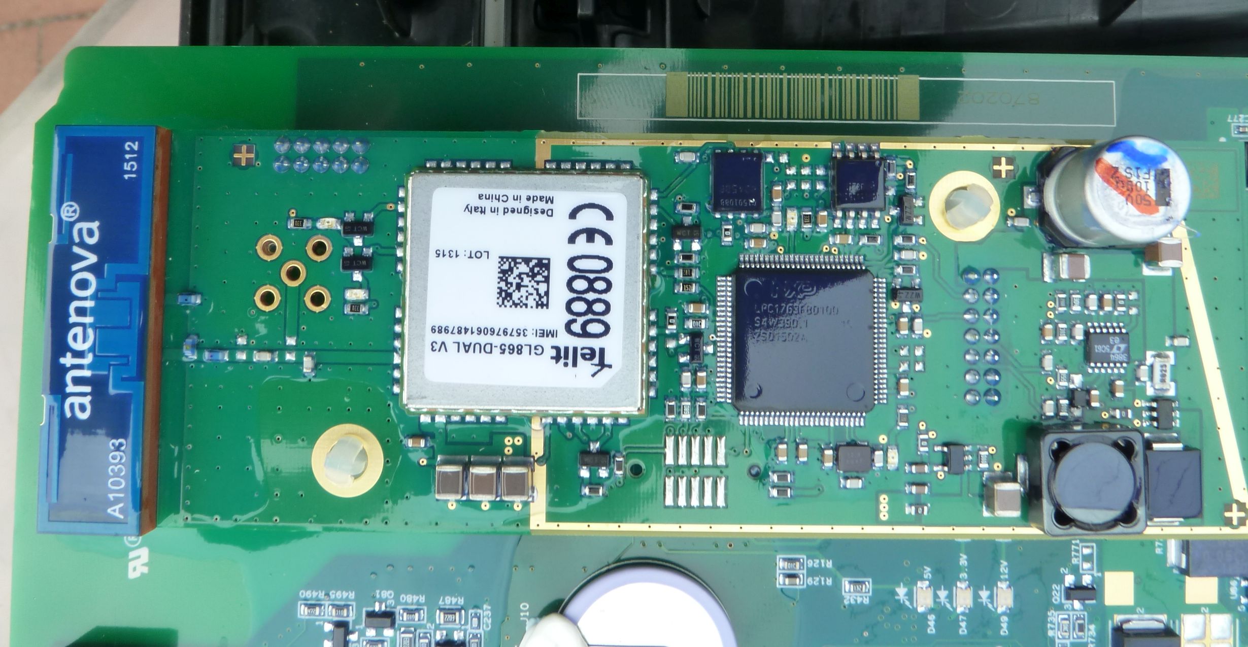
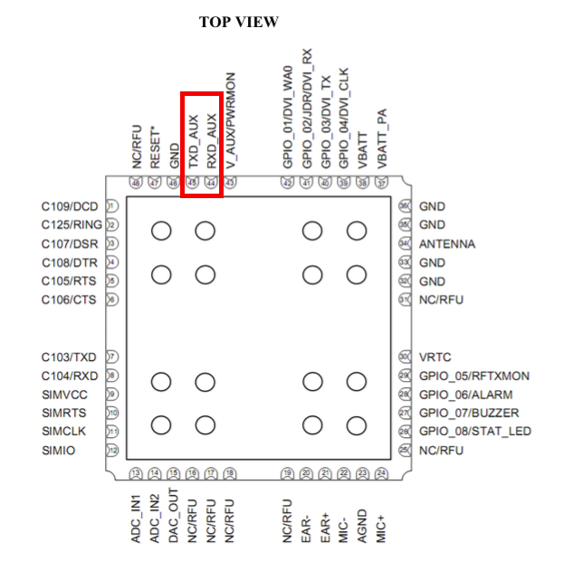
GSM-Modem (Connect)
Battery
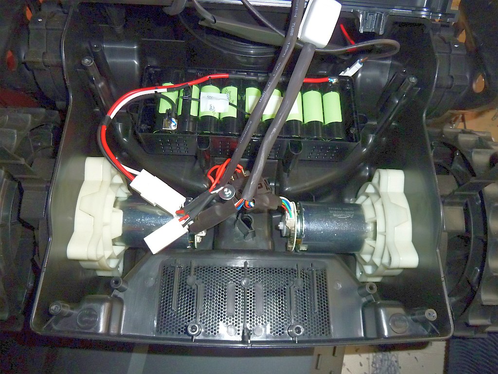
Li-Ion, 3 * 9 (27) Zellen, 32.4V, 3Ah (97.2Wh)
GPS (not found in Connect)
u-blox Neo 6m (WAAS, EGNOS, MSAS, GAGAN), 50 channels
Reed-Sensor (not found in Connect)
Reed-contact (for both free wheels) – detects ground: MEDER MK03-1A66B-100W C9/A
Battery Switch
Compass (Connect)
Compass (6W14A, NXP RG417) is located at the front, compass probably embeds acceleration sensor (to tilt-correct compass values).
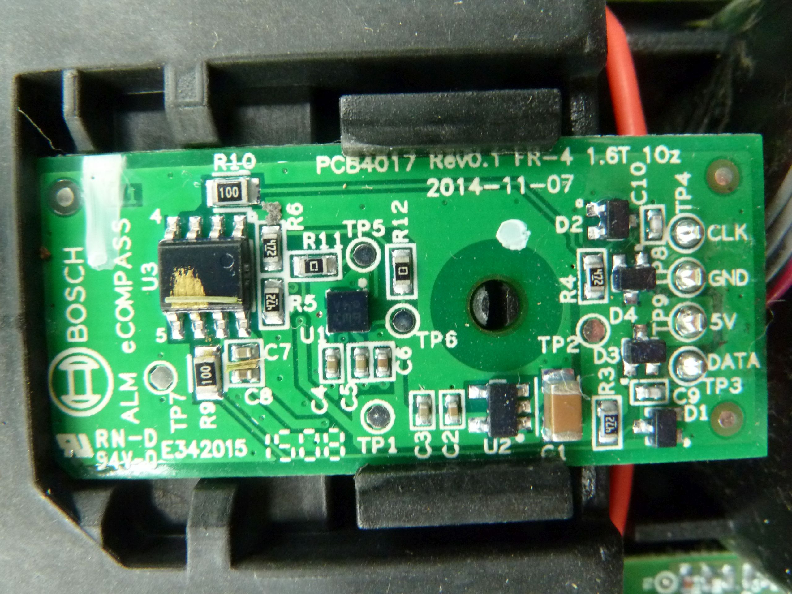
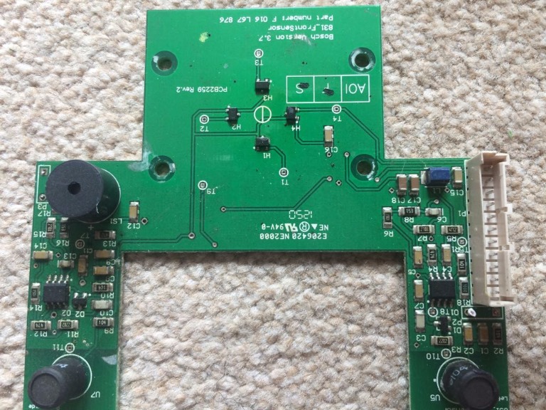
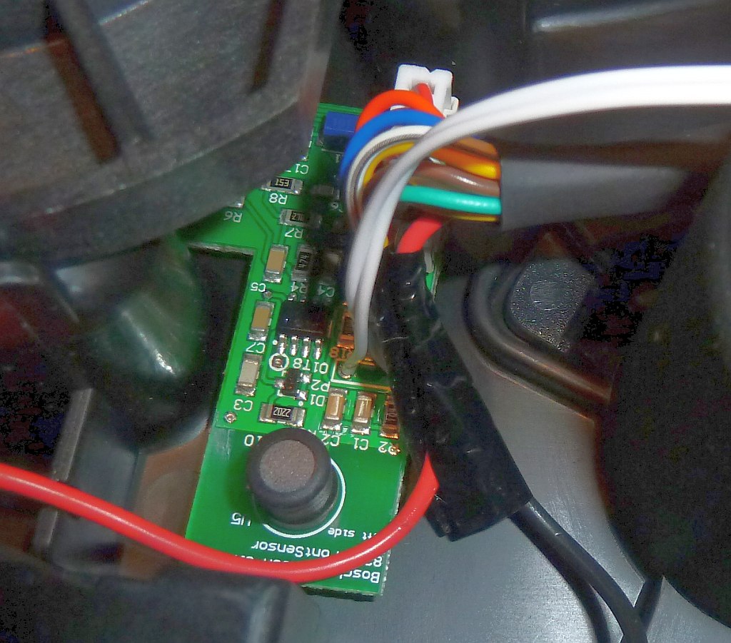
Perimeter receiver (Connect)
Two coils and amplifiers (MCP6004STE 1439, MCP6002E) are located the the front. For the perimeter tracking, the left coil is centered on the perimeter wire.
Perimeter sender

Indego Connect measurements (Wire diameter 1mm): At startup, the sender ‘probes’ within 5 seconds from 5W to 25W, then returns to 5W again.
Measurement  A       B          C      D          E          F
             220m    120m       100m   50m        20m        OFF
Upp          63      42         20     12         4          -
Umin         -19    -13         -7    -4         -1.9        -
Umax         44      28         14     8          2.2        -
PowerW       5       5          5      5          2.7        3
ROhm         7       4.7        2.4    1.2        0.6        -
Measurement B: repaired 120m wire, ROhm would be an effective 156m wire
Measurement A: includes the repaired 120m wire (see measurement B)
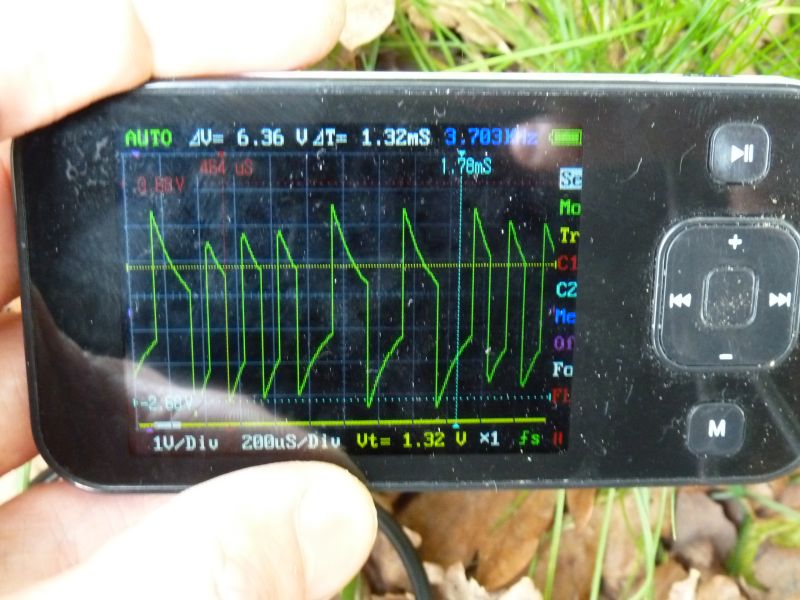
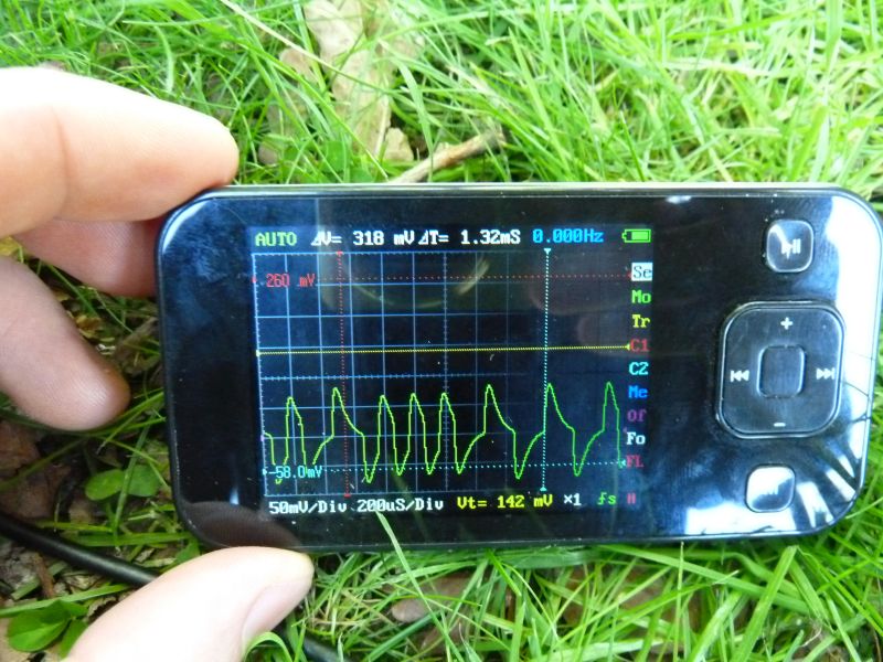
Signal sender, perimeter open:
Signal sender, perimeter closed:
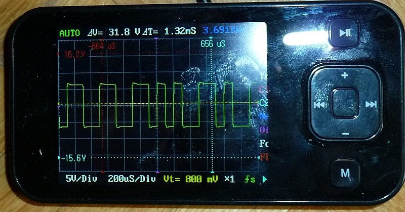
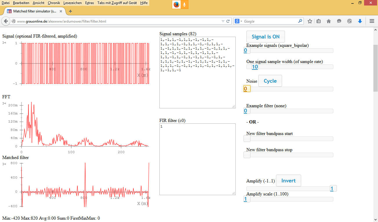
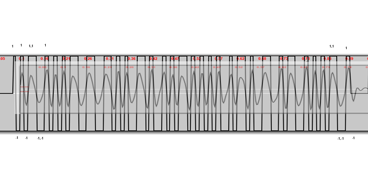
Signal shape: square, pseudo-noise signal code (10 Khz samples), that means the sequence “1,-1” would be a 5 Khz square, and the sequence “1,1,-1,-1” would be a 2.5 Khz square. The signal code evaluation could be performed by a Matched Filter (correlation). The average frequency is 3.7 kHz.
The signal (Indego Connect) is 82 samples (8 ms long, repeating every 100ms, so 92ms silence) and can be detected by a correlation:
1,-1,1,-1,1,1,-1,-1,1,-1,1,-1,1,-1,1,1,-1,-1,1,1,-1,-1,1,1,-1,1,-1,1,-1,-1,1,1,-1,1,-1,-1,1,-1,1,-1,1,1,-1,1,-1,1,-1,1,-1,1,-1,-1,1,-1,1,1,-1,1,-1,-1,1,1,-1,-1,1,-1,1,1,-1,-1,1,-1,1,-1,1,-1,1,1,-1,-1,1,-1
The result of the correlation is polarity (sign of the correlation) and the signal strength. The polarity tells us if the robot is inside/outside, and the signal strength tells us how far it is away from the perimeter.
Nice work. And a pretty cool product…
Now there are different versions of the Indego depending on the required mowing surface. But the hardware seems to be the same.
Question: Can the 600m2 version mow twice the surface?
And if it cannot, which config or firmware change or mem upgrade would be required?
Thanks!
Hello Johnnie,
I don’t know the exact differences but I also think that the hardware is the same except the battery capacity is different. The mower will do more breaks to recharge the battery. On our 600 m^2 surface the Indego 1000 does make 3 breaks for the complete area (each about 30 minutes) for recharging.
Regards,
Alexander
Thanks Alexander. 🙂
I will check once I get mine if a battery upgrade is possible (and economical…)
Hello Alexander,
1. Your IC partlist shows an RS232 level shifter MAX232.21.
Have you tried to connect an RS232 terminal (e.g. TeraTerm) to that interface?
I might me very informative to know, what messages the indego sends.
It is to be assumed that an operating system is running on the uC.
Maybe it is possible to login via RS232.
2. Do you have any informations, how the 6 keys are connected to the ARM CPU?
Direct to ARM GPIOs or is there a keyboard controller between?
Hello Rainer,
No need to reverse-engineer something – we have developed a fully open source mower that operates like the Indego and that you can adjust to your needs:
http://wiki.ardumower.de/index.php?title=Ardumower_Sunray
http://www.ardumower.de/index.php/de/forum/software/827-ardumower-software-sunray
Regards,
Alexander
Hello Alexander,
interesting project!
My target is not reverse engineering.
I just want to make the Indego WiFi capable.
The idea is, to attach an RaspberryPi to the Keyboard/LCD interface.
No nice solution, but it should help to recover the Indego by remote access.
(Enter PIN after pseudo error, Restart ….).
Regards
Rainer
Hi Rainer
This is my project as well – have you made a solution ?
Cheers, Malnitz
Hi Rainer…
Did you finish your project with Raspberry and Indego ?
Hello,
I have had a Bosch Indigo for two years. The first year it worked perfectly. Since one year it stops alle the time indicating error 101 – The mower was lifted. This happens on the tiniest irregularities in the gras. I send the mower to Bosch three times for repair, but each time the problem returns after a couple of days. Do you know if the sensor can be adjusted for sensibility? Or can I disable the wheel sensor if Bosch is unable to solve the problem? (sending it back again today)
Best regards,
Jan
Hello Jan,
You can tape the movable metal pins in the free wheels, so that the free wheels cannot drop down. It works, but then your mower is not able to detect anymore if its lifted. So really not a recommended solution, but a solution if Bosch is unable to solve the probem.
Regards,
Alexander
Thx for your rapid reply! I will give Bosch one more chance to solve the problem… if they don’t get the job done, i know what to do.
Best regards,
Jan
I do it after same problem and now is ok. But new error begin quickly 149 – mower out limit perimeter. Can anybody help by recommendation?
Hello Jan, replying to old thread for benefit of others:
If you indego – that has run for some time, perhaps a couple of years – gets stuck all the time for small bumps in the garden, the problem might simply be dirt.
The wheels need to go back quickly after a bump before the sensor will say it has been lifted. If the frontwheel construction is dirty, this will take too long.
To solve: Simply take a correct torx screwdriver, some cleaning brusch (old toothbrush works) and perhaps some fluid – but then wipe off very carefully and dissassemble frontwheel carefully and clean parts to ensure smooth operation. Repeat for other wheel.
BR! /marcus
Dear Marcus, all,
Recently my mower stopped working, also with the before mentioned 101 liftup error. I’ve followed some tips that I found on this and other websites, cleaned the wheels, disassembled everything up until cleaning the joystick. Even with all sensors disconnected (the mower still starts) it keeps on returning the 101 error. Seems like something in the central unit does not add up. Or the information from the sensors does not reach the central unit. Does anybody have any other tips?
Kind regards,
Arjen
Hi Arjen
did you ever find solution ?
struggling with the same…. (like quite some other people it seems)
thanks & regards
Jorrit
Hi Arjen
Any luck with the 101 Error ?
I have the same on my mower
for anyone still encountering this issue:
check the voltage that is set by the divider made of R60 and R68. It sets an upper voltage for the hallsensors that if exceeded also trips the lift detection.
in my case it crept down to 4.4V which is below the max voltage the hall sensor can output (around 4.6V). Since the max field strength is not in the most pushed in position of the wheels but somewhere in the middle, this explanation also fits with the observation of Error 101 being thrown on small irregularities in the lawn.
Hi,
Thank you for sharing all this information with us.
If I understand correctly you didn’t find a GPS module on the „connect” version of PCB but I wonder how then this version is capable to generate a map of the garden and show it on the app?
Currently the Indigo 800 is priced at 200 Euros less than its Connect 100 brother and according to http://www.tecky.de/review/bosch-indego-rasenroboter-und-maehroboter/ + the fact that you didn’t find a GPS module on the Connect, I would go for the 800 Model (I want the GPS). Am I correct in my judgement?
Br, Bart H.
Hello,
The Indego uses integrated motor encoders to measure the traveled distance of the robot (cm). Additionally, it uses a combination of gyro and compass to measure the traveled course (degree). Both, distance and course gives the current position (x, y). Of course, the motor encoders measurements are relative measurements (based on some start position 0,0) and experience small measurement errors (%) yielding to a wrong position after some time. To correct the position, the perimeter wire is used.
GPS would be inaccurate as GPS is never more accurate than 3-6 meters. The reason is the long distance the GPS signal has to travel, and not straight signal path (signal reflections on the ground).
You can see here how this concept works (Ardumower is a DIY robot mower):
http://www.ardumower.de/index.php/de/forum/software/827-ardumower-software-sunray
Regards,
Alexander
Thx for your reply.
I finaly decided not to go for the bosch indigo (dumped at 799,- in some Belgian stores). I ordered a Robomow MS1000 with a cuting area of 56 cm. Plans are to combine it later on with the arduino (or other) intelligence to make it more energy efficient.
Regards, Bart
Hi,
Great page! Thank you for sharing!
I have two Indegos; one 800 working at my old mothers house, and a Connect 1100 at home.
I wonder; have you tried to dismantle the gear motor outer end? I want to try to reduce noise from gearbox. I guess that’s what is inside the white plastic box? Silicone grease should probably work well…
I also want to add an extra battery, but want to build one myself. The original is very expensive. But; what about the white cable?
Best regards,
Terje
Really nice job with your Web GUI !
How did you get all the API available commands ?
Regards,
ThomasM.
Hello Thomas,
Thanks. I found them in a German robotics forum (http://www.roboter-forum.com/showthread.php?10567-Bosch-Indego-connect-Anbindung-an-Portal-IFTTT/)
If you have any suggestions, feel free to post them.
Regards,
Alexander
If you want, I can realize the French translation, if you provide me all the English texts 😉
Hello I have a great problem with my indego
And bit seams only this site has some hardware information on it
My indego won’t start the display stays out
Can somebody please tell me what currents are necessary on the connectors for the pcb
Will leds light up when circuit breaker is in
My battery has a charge from 35v which seams a bit odd to
I think it’s an easy problem which can be sorted out
I don’t want to send it in again for a pricey repair
Thanks
Hello Joerg,
I Have exactly the same problem. Did you get an answer?
Thanks!
Alan
Bonjour Alain,
j’ai une indégo 1200 connect et j’ai le même problème que celui que vous aviez eu en 2018 : batterie chargée mais l’indego ne démarre pas, l’écran reste éteint.
J’ai vérifié :
– alimentation de la carte mère OK (36v)
– bouton “STOP” OK : contact fermé aux bornes de la carte mère)
Aviez vous trouvé la solution à votre panne?
Bien cordialement
Patrick
Bonjour,
j’ai une indégo 1200 connect et j’ai le même problème que celui que vous aviez eu en 2016 : batterie chargée mais l’indego ne démarre pas, l’écran reste éteint.
J’ai vérifié :
– alimentation de la carte mère OK (36v)
– bouton “STOP” OK : contact fermé aux bornes de la carte mère)
Aviez vous trouvé la solution à votre panne?
Bien cordialement
Patrick
Hi,
cooles Tool!
Kleine Korrektur: Der “Service-Zähler” sind inhaltlich die Netto-Betriebsstunden … Brutto-Betriebsstunden – Ladezeiten
Also “Service-Counter” = “Netto-Betriebsstunden”, die Zeit in der wirklich gemäht und nicht geladen wurde. 😉
Danke Dir 🙂 Hab’s korrigiert 😉 Gruss, Alexander
Hello from France,
Congratulations for your nice work and Web App !
Yesterday I received my Indego 1000 connect, I just have to install the limit wire, I already registred my Indego and I hope I will finish it today to be able to play with this toy 🙂
Do you know the maximum voltage of the battery when charging ?
Mat
Hello Mat,
Have a look at the section ‘charging station’ above. The charging voltage is 42v.
Alexander
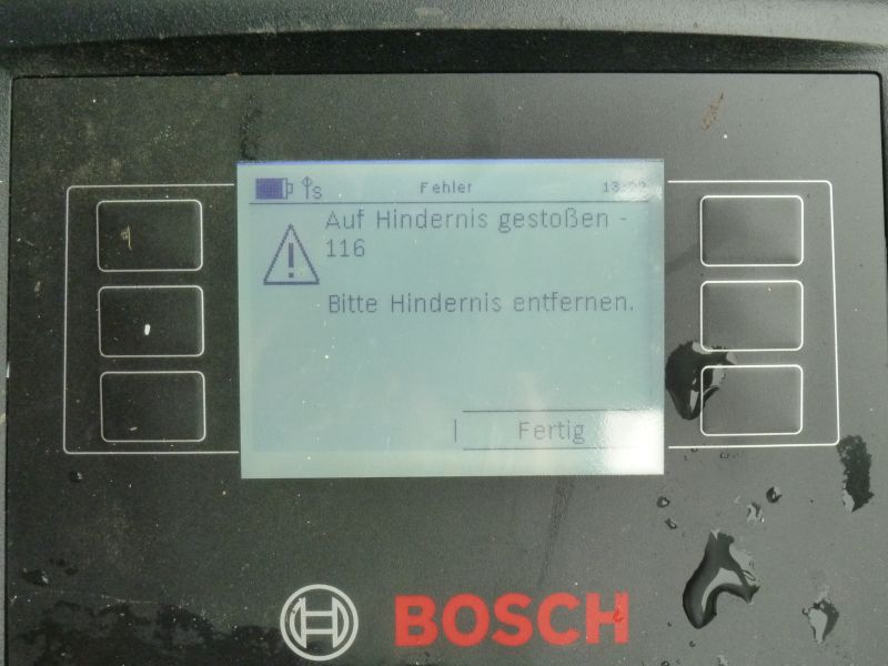
I have had my indigo connect 1000 for about a week now and generally pleased except for one fault. 60% of the times it goes in to dock to recharge it throws an error 115 Permanent Tactile Detected. In other words it thinks it has hit an object rather than the docking station. Of course this requires me to go and put in password to clear it. Which is hopeless, and Bosch are yet to come up with an answer.
What firmware does it have? I have seen these problems only with firmware 728. After downgrading to 647 these problems did go away.
00647.01043 (75 users)
00728.01043 (52 users)
00824.01043 (2 users)
00529.00903 (2 users)
00529.00943 (3 users)
00712.01043 (14 users)
Mine is 0712.1043 and it behaves like that exactly. Error code 115 while docking alone. But charging in between is perfect. Spoke to Bosch support and they advised to reboot. Same effect still.
I have the same issue.
I did notice the robot had a difficult time docking because the charging pins seemed too high for the robot, causing it to bump slightly when docking or undocking. I think that the height of the front wheels of my robot are much lower then normal (maybe because of the many bumps agains stone borders). So as a test i raised front part of the docking about 4mm (using a thin multiplex plank). Afterwards, it docked and undocked without any errors for about 2 weeks.
Unfortunately the problem returned after 2 weeks. Sometimes i see an error 115, but mostly it just detects a non-existing obstacle while undocking (after about 20 cm).
Did you ever found a better solution?
after winter time on the dock, now my Indego 1000 has exactly the same problème with 115 code after 20cm undocking, I clean the interior of the indigo (some little water in the front ) but problem still the same, what was yous solution ?
I just solved the problem ==> I removed the joystick assembly and unmount each part and cleaned it, I cleaned the mainboard which had dust on it and around the sensor and now my Indego 1000 connect is perfectly working 🙂
Hi, i have had my indego now for 3 years, and sudently i have got problems with both of the coils in the front, i found out it was water ingress in the mower, and it goes past the wire all the time. And ceep throwing up error code: 149
I have 5.8 firmware. Do you have any suggestion on wath to do with the front board?
Best regards stein
Have you tried to contact Bosch for a front board spare part? If they cannot deliver this as a spare part, maybe you can send me a high resolution photo of the condition of the front board. It is often possible to repair water damaged boards (drying them and repairing circuit paths).
Email with pictures sent. I think i need a new pcb board, bit do you have some sites that deliveres parts for bosch indego?
Do you know if i can update my indego by myself? Its immbossible to find firmwares online to download
You may get some spare parts directly at Bosch (you can find your Indego model at the top of my blog, e.g. 3600HA2103):
http://www.powertools-aftersalesservice.com/public/Boschlg?lgRedirect=true&country=XZ&lg=en
Unfortuneately, they do not seem to offer PCB’s at all. However, they offer a repair service, so maybe try to contact them and ask for a repair?
Hi. Can the web interface be used to steer the mower outside a perimeter wire area? I would like to mow a small area of grass where there is no wire. Thanks.
Hello Alexander,
it was since a lot of time that I was searching a web interface for the Bosch Indego that would give more details on the status of the mower and I finally found it thanks to you!
I find it very useful because I am investigating a strange issue on my Indego: during a mowing cycle, very often the device goes in status “519 / Idle in lawn”.
However it does not give any other warning messages. After that, if the mower receives a manual command of mowing or return to dock, it goes in status “514 / Relocalising”, and finally resumes its operations. Of course if left unattended when it is “Idle in lawn” ultimately discharges the battery.
I am puzzled about what could trigger it going in that mode, do you have any advice that could help me solve this problem?
Thank you very much!
Hi,
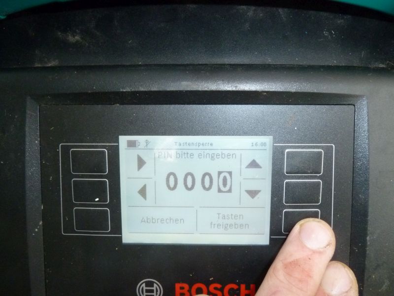
I’ve got following Problem with my Bosch 3600ha2100. Somehow i lost the pin. Is there any Solution to reset the pin? Bosch Service warnt to have 250€ for fixing The Problem. I saw in your pic that On CPU is a reset pin?!
Thx
Hi Alexander,
impressive work, and very useful.
I was unable to find out elsewhere, so sorry for asking: do I assume right the charging stations are mutually inter-compatible with the mowers?
Dumb me, I have mistakenly left my charging station on during winter and thick layer of snow flashed it through during melting :(.
I have 3600HA2101 – Indego, 230V/EU: would it work with charging station for 3600HA2200 – Indego 1300, 230V/EU?
Many thanks for help in advance,
Tomas
Hello,
Is it possible to use lcd from Indego in the Indego 1000 connect?
Hello, Yes, I think they use the same LCD (it looks the same).
Thanks
Please I need help. Since yesterday I can’t connect to my Indigo via app with my mobile. When I try appears this message: “Logged in on another device”
I think you cannot use PC web interface and mobile App at the same time. Is the problem solved that way?
I have not used them at the same time. Maybe the problem is that I’ve used an IPAD (IOS) for the web interface. I will try to reset the mower.
Thanks
After reinstalling the APP it works correctly.
Hello.
I would like to use a gps tracker for my indygo. Need to use 5v power supply. Is it possible to connect to indigo?
Best regards
I have problems with the indego not sensing the border wires. I thought I shoul try a factory reset but I don’t know how. Can you help?
BR….Yngve Johnsson
A 4 amp pcb fuse was blown in the charging station,.i have replaced it and now i have error cod 149. Do any one have a idea about this?
Hello!
Impressive collection of information and creative software work on the Indego You are gathering on this webpage.
Do You have any idea wether Your web interface will work with the new Indego models that are coming this spring? Bosch are launching two new models these days, Indego 350 & 450 Connect.
And do You know if there are major technical upgrade on these models?
BR…Pål
I think it will work as the web interface speaks to the Indego server located at Bosch and this protocol will be the same for all models.
http://grauonline.de/alexwww/indego/res/system.png
Hello
Will the mower work with another base, from another mower?
Best Regards Adams
Possibly with some other Bosch models. If you mean other suppliers – I’m afraid it won’t fit.
Hello, I am using Indego 1200 Connect. How to find out if I need to replace blades? Will Indego inform me in the future that blades need to be replaced?
Is there anyone that can answer this important question? Thanks.
As far as I remember, the App is informing you, when the blades are used for a long time and will link you to the shop. You have also the possibility to reset the counter for that blade-usage inside the App.
Thank you Ingolf very much for your answer. I know that the app give a chance to reset the counter but I do not know that it will inform about the blades to be changed. So as I understand just need to wait until the app will show /pop up/ proper message that is time to replace these blades.
Ok will see.
OK after 100 hours this App showed alert that I should check if the blades are still in good condition. I think this will be every 100 hours.
Hi,
I’ve been using Indego 1000 Connect recently. Works well, however can’t pair it with my mobile. The antenna sign is crossed on a display and when I try to check the signal strength it is constantly -128dB (I believe it means none). Did few restarts and tried to install/reinstall an app on a mobile and a tablet but no progress has been achieved. Also, I tried few different location (Central, Western, Eastern Europe) but it didn’t help.
Any help more than welcome
cheers
Marek
i have exactly same problem!
bosch already replaced gsm module but no change.
i suspect some softwarw issue here… is there any way to make kinda hard reset for indego? seems like factory reset still keep some data (date, year etc) in memory.
Should perimeter voltage be available in the charging station immediately at voltage input or must the charger be synchronized with the mower? I get no voltage on the perimeter contacts at all.
Hi,
I’ve got an indego 800. It is reporting lift up alarm activated – 101. I’ve taken it apart and checked the front wheel hall effect sensors are clean and seem to be working correctly. is there any way I can over ride them to check where the fault is ? Any assistance would be appreciated. I’ve called Bosch but they said that they haven’t been trained on the product !!
Thanks
Kevin
i also have this problem
did any one find a solution?
Hello,
I had the same problem and found no other solution than to remove the small electronic card inserted inside the front wheel assembly. What I find really strange however is that I had to do this on BOTH wheels, so now there is no safety in case of lifting the mower. But at least it mows !
Hi
I have the same problem with my 1000 connect.
How did you remove the pcbs ?
Did you remove them fron the mower ?
I think also its the mowing thats important 🙂
Thanks in advance
Hello,
I’ve got indego 3600HA2100, it doesn’t work, at least because of Disconnected battery inside. I don’t know to which plug should I put the battery in, as there are two, like on this picture (I found it in your article) and they are labeled CR and CL:
http://grauonline.de/wordpress/wp-content/uploads/indego_battery.jpg
Which one should I use, can you help me please? Thank you in advance.
Br
Chrystian
I assume it’s for a 2nd battery, and as far I can see from the picture both are connected in parallel, so it doesn’t matter which socket to use. However I think the sockets are coded (plug CR will not fit onto socket CL and vice versa) so you cannot mix them.
Hello thank you for your quick reply. The plugs are equal. And they are all going to separate pins. The main switch it is double one in my case. On one of your pictures above, you show how to wake up the MB without having it connected to the robot; you just put the power supply to pins located in the upper right corner. In my case, also the pins below are used. And they are connected exactly with the second plug.
Then, I think I will not make any mistake, if I’ll use the plug connected to the upper pins, as you did it.
Thank you. BR
Chrystian
Hello,
I have good news, the robot is a life. I used the CL plug, I managed to establish magnetic connection to the docking station, improve contact on battery minus pole terminal and find broken wire in cable from Trafo to docking station. The robot is talking now, the battery is almost full, as next I’ll try to force it to move. I hope I can connect short loop to the station, just to close the circuit to get it moving instead of going immediately to garden, am I right? Anyway, thank you for your help and the article. It was very helpful.
Best regards
Chrystian
Excellent! Yes, a short loop (20m) should do the trick, so the charging station as well the robot can detect it.
Hello, I have the same problem, when i connect the display on a desk it will start up but when i put it back in de robot i am unable to get it started, i used a magnet on the charging station and the voltage drops to 2.6V but nothing happends, am i missing something? Best regards , Günther
Hi!
Thank you for doing this “tear down”. It is perfect for me at the moment because I have an Indego (not connect) where the right perimeter sensor does not work. I found a lot of dirt on the board and it might look like the cause. I cleaned the board but it looks like I made a doo-doo when assembled it som I managed to rip off two of the hall sensor on the “joystick” board. I cant read the name on the board and was hoping you had high res pictures of the sensor board – if you could check I would be really greatful! (Looks like it says “324” but Im not sure)
Best regards
Stian
Acutally someone else discovered this piece of a puzzle: ” I think they are linear hall effect sensor ICs with analog output. Possibly Allegro A1324. The IC’s have 324 written on them.”
Is it possible to replace the display for some other one, or can you find a pinout of the display truly (maybe a schematic). My damage is crushed.
It would be really interesting to know as these displays often break – I had no luck so far to find anything about this display.
And how would anyone be able to record a movie like entering the menu from the moment the lawn mower and delete the old garden to make a new one. Then I may be able to program the mower again without using the display.
Really difficult as menu is slightly different from firmware to firmware. Also, currently I do not have any Indego here (did build an Ardumower http://www.ardumower). Maybe you could do the same and use the Ardumower PCB to control your Indego?
http://www.ardumower.de/index.php/de/forum/perimeter-receiver-and-sender/1233-reducing-power-usage-heat#11967
hi alexander,
thank you for your time and effort into this project. i recently got an old 3600HA2100 indego but systemerror 200 (mainboard error) appears. i am very interested in using your ardumower PCB to control the indego. did someone already made it and documented it. unfortunately i do not have the time (because of 3 little kids and fulltime job) to try allone.
best regards and cool site, martin
Will this display be compatible? LM240160G http://www.ukai.com/documentos/004681-LNK04522.pdf
No idea. The Truly displays (TSF 8G0661FPC-A2-E in Indego and 8G1293FPC-A2-E in Indego Connect) have 20 pins, the LM240160G has only 16 pins, so the pinout is probably different. The controller may be the same, or it may be different. Without information from Truly we cannot do anything.
This LCD won’t work because it uses a ST7529 controller and the Bosch LCD (at least the 1000 non-connect) uses an UC1698u or compatible.
I think this is a view based on uc1698u. With the lcd going out 35 pins it is the same in and truly. The same is the first pin is the power supply. http://www.farnell.com/datasheets/1934393.pdf?_ga=2.49301606.1941951674.1495711450-1900979243.1495444905 http://pl.farnell.com/midas/mccog240160b6w-fptlw/lcd-cog-240×160-fstn-black-on/dp/2219022
I think the chances to get this running using another display are very low – Even if you find out the I/O lines etc., the display will probably send some ID (display type, revision etc.) on request to the mower. If it is not the expected chip type (and revision), the ID may be different and the mower will not start?
If that LCD would still be available and not too expensive, it would be worth a try. The connector is not compatible with the 1000 but I have no details for the connect Version of the LCD connector.
Hallo.
My power supply to the charging station was broken so i bought an other aftermarket DC 42V 3 amps charger on eBay, when i hooked it upp with the Indego Docking station everything seems to be fine and the green LED on the top of the docking station were lit up, then i pushed the Indego into the docking station and all that happens was i litle click sound from the Indego and the everything is totally dead. No gren LED on the dockning station etc. Amy clue what can have happend?
Thank you
Could be the 4A fuse on the docking station board that has blown.
Hi,
I’ve only just started to use my Indego 1000 connect and almost immediately regretted my purchase. I have several issues with it but these are the main ones for now:
1. faulty error reporting: I spent the better part of 2 days figuring out why on first run the mower reported the error that the wire to the base station was not straight. As it turns out there was nothing wrong with the wire – there was simply not enough room around the base station for the robot to manoeuver.
2. a week into using it, suddenly it starts to stop randomly with the error that the left wheel is stuck and should be freed first (216). I have checked and cleaned out the wheel repeatedly but the error just keeps on coming back. I wonder if this is another faulty error report? Anyone?
3. Probably the biggest issue I have: the mower does not cover the entire garden, even though the map says everything was mowed, there appear to be “patches” or lines of unmowed grass. I googled this and found that people have been complaining about this since 2015. You’d think that by now Bosch would have issued a firmware update to fix this, but no.
I’m probably to blame since I didn’t do enough research prior to purchasing this robotmower, but I was blinded by the brandname “Bosch”, which – until now – used to mean quality.
Hello, I am using my Indego 1200 since few months cutting grass every day /level 5 manual start/. It is working great, no errors and the grass looks nice. Every 100 hours I am changing cutting blades for new ones. I do not observe any issue up to now. Sometimes it left uncut area and reports 98% done /never reports 100%/ but during next day run it move it and it is acceptable. Overall the grass is cut ok. I started with level 7 and now using only level 5 /sport grass/. I would say it is real good product. I did installation very careful looking for all recommendations from Bosch. I am happy user.
A small update. Since I’ve last posted, the mower was returned to Bosch for repairs. In spite of the problems i’ve had with this mower, I am quite pleased with the way Bosch handled it, they’ve pretty much done a complete overhaul, changing many parts for new ones, even though they were unrelated to the error – which as it turns out, was a faulty sensor.
They have repaired my unit free of charge and I am eager to test it when the weather gets better.
I have Indego 1200.
It works good untill now.
At the display is error 130
Cutter motor load too high.
I switch off check it and switch on.
After it I put pin and automatically get this error. Is it possible to reset?
Hello. type 3600ha2100. Worked fine. There was a moment when stopped and the pit and skidded wheel. After that worked fine. At the time of mowing was disconnected from the network. Then when you install to the base station error seems 194 does not see the perimeter. Departs from the station stops, the meter will pass stops. Did reset to factory settings. The error on the perimeter is not. Press the button to memorize the map to move around the perimeter of error “Low battery voltage or battery temperature out of range. Mower will start when battery condition is ok “. Checked the voltage at the terminals of the charger base station 4.6 v when there is a connection with the mower voltage 30.6 v Charges in a minute heard in the mower relay click, the voltage drops to 4v then back to 30v. And every minute the sound of a relay click. Here I wanted to ask what could be ? How can I fix )? Thank you )))
did you fix your issue?
Hi. I need to replace a signal coil on my Indego 800. Do you know the component id? Looks like it has 109.01 on it and 104. Thanks.
Hi,
Love this blog…so good to find someone who is willing to share information that is not freely available rom Bosch.
Hope you can help with a defect…..
I have an Indego 3600HA2 102. It was working fine, I took it in after a cutting session but it was showing it needed a charge. I didn’t have time to leave it on the docking station. Not sure if, in my haste, I forgot to switch off the red key. The following day it would not connect. Green light was flashing randomly and there was a loud clicking sound, like a relay click, louder than the normal soft click heard when first placing the mower in the docking station. Initially there was a display error telling me to check the perimeter wire or docking station but now the screen will not display anything at all.
I have moderate tool skills (trained and worked as an electrical aircraft engineer over 25 years ago when flat screen technology was appearing in executive jets – am very rusty now!) but I don’t have the technical knowledge to the level I have been reading on this site.
I don’t want to send the mower back to Bosch as it seems it is likely to come back with the same fault!!
Hope you can help.
Kind regards, Sue
Hey guys. Since a few days the indego Webinterface is temporary not available. Error code 0. could someone tell me what happened?
Thanks for the interesting blog. It looks like the Web interface stopped working. Since days I get the error “Error: service temporary not available (0)” but the Bosch app is working. Did Bosch changed the API?
Thanks for your help. Best
Andreas
I got a problem with my Indego 1200. At the startup the display says ”Free! Translators from Swedish” e-compass failure code 57, contact service IF the problem remains. anyone know how to fix this at home?
Hello, as an user of Bosch 1200 Connect I think Bosch can improve the way mover is cover the entire garden. What if Bosch can give this opportunity to us users. Lets imagine you place your perimeter wire in the garden as you like and then the mover during first run create the map as today. Then this map is available to us through special Bosch application. So we can open the map on our computer or tablet an manually design the path how our robot will cut the grass. We will decide the way it will follow by simple drawing the path over the map. Then this algorytm will be uploaded to robot memory and it will cover 100% of the garden each time. There will be no spots mover will skip and everyone will be happy, Bosch and the user. This change in approach to Customers will be revolutionary and other companies can apply this as well. The reason is simple no one will know better than we how to cut and cover our garden how to optimise the coverage and hot wo go to difficult parts of the garden. We will design perfect coverage as we wish. Hello Bosch can you do this as an option for us?
What do you think about my idea?
thanks,
Zbigniew
Hi –
My 3600HA2102 has failed. I have heard bad reports about the Bosch service centre in the UK – it takes months to be returned. Can I send it to you to be repaired??
Sue
hi
really nice page!!
we also have bosch indego 1000 connect model and are very happy for now. it is working now for 3 days and cutting app. 1300m2.
it took a time for the first run (mapping, runing around trees) and we also decided to leave 7 trees that are “bigger” without perimeter wire, other 10 (younger trees – 2 years old) have 30cm distance circle around… for now it is moving superb!
since you are really a pro, please tell me if you have figured out how to “connect” bosch indego 1000 connect model to some other software… we have fibaro home automation and we also have netatmo weather station that is included in home automation…
So i would like the indego to be the part of Fibaro home automation system. Do you have any ideas how to make this? I have searched over the web already.
Please respond to my email if possible
regards
ales
Hi,
Does anyone know how to resolve ‘perimeter wire not detected error’? I got my 1200 connect out of storage for its 2nd season and I persistently get this error and it won’t mow. The wire is intact – I checked both ends with a multimeter.
Same problem for me, if turn of (remove) AC cable from 220V and turn on again, after 1 minute Indego works again. But sometimes after 2-5minutes same problem again. I heard that this can be perimeter sensor problem. I checked with multimeter all cable is good. Any solution?
Thank You
Harold
Hi Owain,
I seems to have a very similar problem. The Indego claims there is an issue with the wire but I checked it with an ohmmeter and get 5.2 ohm. I tried with a new wire but shorter. Indego still report issue with wire.
Did you fix your issue? How?
Best Regards
Didier
Hi Didier
now I have the exact same error – wire is OK but Indigo reports error. Did you or anyone fix the issue ?
Kind regards
Dennis
Hi
My Indego 1000 suddenly returns following error, without any prior incident :
“Ecompass error 57 : Ecompass not responding – contact service if error persists”
switching off and back on the next day has helped once to start the mower once,
the robot mowed 2/3 of surface, then I found it after a few hours in the docking station with the same message
any clue what to do before turning to expensive repair ?
txs
Luc
Same problem for me after cleaning the joystick mainboard which had a 115 error, I cleaned contact and compass board but everytime I turn on the indego 1000 connect , now I have this compass -57 error :
Erreur Compas- 57
E-Compas ne reagit pas
Contacter SAV si erreur persiste
software version 00837.01043
I have to learn my new garden but after following the wire until the base, I can’t click to indicate the base then I can’t learn the garden :'(
What to do ?
Great tear down of the machine!
I just ordered a Indego 1000 non-Connect version, found one for half price (400 Euro) so it was a bargain.
It doesn’t have a rain sensor which got me a bit worried but I called Bosch and they said that they send out weather forecasts to the machine which it can act upon to avoid mowing in rain (if you set it up like that in the settings).
How it’s done technically I’m not sure. I thought perhaps radio but after seeing the tear down here it seems the non-Conmect version neither has GSM nor radio? Do you have any idea how it is getting forecasts then?
Same problem. Suspect the magnet in the front. Anyone having experienced what happens if that nagnet is gone?
Hi guys,
I have Bosch Indego 800. After winter the robot stopped to charge itself. I have measured voltage on my charger with a multimeter and I got a result of around 6V. The charger is rated to 42V and 3,5A. Can I assume that the charger is faulty or is it like that that max voltage one can expect is 42A, but a regular one will be around 6V?
Thank you!
Hi Good practice is to charge it every month during winter time. I did this and no problem, works fine.
Hi,
https://www.amazon.de/s/ref=nb_sb_noss?__mk_de_DE=%C3%85M%C3%85%C5%BD%C3%95%C3%91&url=search-alias%3Delectronics&field-keywords=F016104299 shows replacement batteries for the Indego.
Are all suitable for the indicated Indegos ?
I have a 1000 Connect that I didn’t open yet. Can I put the 5000mAh battery in it ? I assume there is a 3000 in it now.
Thx
Hallo,
Ich habe in Frühjahr 2016 ein indego 1000 Connect zugelegt. Zuerst war alles gut. Erst nach wieder Inbetriebnahme in 2017 hat es Probleme gegeben. Es gab immer wieder orientierungs- und Lern- Phasen wo der indego das Begrenzungsdraht auf und abgefahren ist bis er richtige Rillen eingefahren halt. Laut Bosch Kundendienst liegt es an eine Engstelle im meinem Gaten, etwas 1m lang und 70cm abstand zwischen hin- zu Rückletung. Laut KD ist der mindest Abstand 1m. Sie sagten der Indego scheint nich zu wissen ob er innerhalb oder außerhalb der BD ist. Ich habe intuitiv gedacht ich muss das koppelsignal abschwächen. Darauf hin habe ich das BD weiter eingegraben , ohne Erfolg. Dann habe ich ein Trennblech mittig in der Erde eingerammt ohne Erfolg. Bringt es was wenn ich die BD verlängere als ob ich eine virtuelle Hinderniss ausgrenze. Ich habe oben gelesen das damit der Widerstand erhöht wird und eventuell das Signal geschwächt. Was meinen Sie. Haben Sie andere Vorschläge. Ich bin am Ende.
Sorry,
I ‘ve been in Germany so long that i forget which Language i’m Reading/writing. I guess i’d better translate my above post.
In spring 2016 i bought an indego Connect 1000. At first everything was fine. After demothing in Spring 2017 the Problems began. Continued Orientation and learning Phases along the perimeter wire were regular leaving deep slots in the grass. According to Bosch Service this malfunction is caused by a narrow Zone in my garten, about 1m Long and 70 cm width. Service said at least 1m distance between the Wires is required. They said that the indego doesn’t know if it’s Inside or outside the perimeter wire. Ich habe intuitively thought i should try to weaken the Couple signal. So first i tried to bury the wire deeper in the grass. No Change. Then i rammed a piece of sheet Metal between the wires. No change. Do you think it would help if i lengthend the perimeter wire to increase the resistance and lower the voltage (ref. Your article). Like a Virtual obstacle. Do you think it would work ?
Nice to read all of your topic
I buy it in 2015
And first Time with big trouble. Perimetric trouble.
It cannot see the perimetric câble but not all Time ( trouble 149)
First , I do a reinitialisation to factory setting . After it , indigo check correctely the first
10 m and after it lost the cable.
The coils are often the trouble or …..
My first idea, check pcb coils
Hi Christophe,
I have the same issue. Did you find a solution ?
Thank you very much.
Hugo.
Hi,
Can I swap a 3000 mAh battery in an indego by a 5000 mAh version and thus have a longer run-time ?
Or are there other parts to be replaced too ?
Anyone know what a system error 45 is on a Connect 1200?
I have an Indego 800 machine.
After the winter, I have some problems: when I put the machine on the charger, the relay clicks and the display lights up indicating that the machine is charging. The display stays continiously on. But the machine does not start at all. When I remove the machine from the charger, it shuts down immediatly (not possible to activate the display at all). I have already replaced the battery by a new one, but the problem is still the same.
Something else that could indicate the problem: normally when the machine is on the charging station, you have the possibility to press a button to start working immediatly, but this option is not available (normally it indicates “start now” and now there is just “…”). And when I put the machine back on the charging station, it always says that is has been a long time that the machine saw the wire around the garden.
Does anyone have an idea what could be wrong?
Hi Jos,
I don’t have a solution to your problem, however if it makes you happier, I have more less the same one 🙂 Moreover I am not able to unlock the mower (the LCD keyboard stopped working). I’ve replaced the old battery too. As soon as I find out what the problem is, I’ll let you know!
Hi Dariusz,
Dig you working out the problem with the display buttons? My mower works great but I can not unlock it any longer due to that the buttons have stopped working.
All the best,
Sören
Dear both,
I’ve just got a second hand 1200 connect unit for our smaller garden (already had an older 1300 for the big garden) and have this same problem. Mower starts when docked, says “please wait while your unit synchronises” and then switches off with a click. Can’t get it to work by pressing buttons.
Did you solves your problem?
Andre
Hallo,
gibt es eine Chance, dass das Interface für den Indego 400 Connect angepasst wird?
lg
Hi. I have an indego 350 connect (3600hb0100) and rhe robot give me (sometimes) error 107. I have to restart docking and robot waiting at least 20 minutes to restart, otherwise error appairs again while booting. Do you know error #107? It seems this error come out if he robot is blocked by an obstacle or when you pause the mowing job. Have you any ideas? Thansk.
Nicola
Hello,
It is a peety that there is not answer to the questions. At least, the writer himself can give a feedback and it can help the other.
I have have an indego 1000 and it don’t want to charge the battery. The voltage to the power supply is 48V. How can i be sure if the charger or the station is faulty? I’m from Liége in Belgium.
Thanks
Hello,
my mower is locked in demo mode (blades do not rotate)
do you know how to disable this mode?
Thanks for this blog
beautiful day
It is possible to control Indego 350 connect. Some api or something, becouse it is twice cheaper then 1000 which is not manufactured, and still avaliable to buy, but it has a lot of issues and a lot of people where writing that 1000 broke down. I did’t found information about problems with 350 version
Hello,
I just bought the Bosch Indego 1000 Connect mower. Before the weekend I started the device on the test area (about 200m2) and it turned out that the mower has a problem with calibration already during the mapping of the garden on the boundary wire. After starting the mapping, the device stopped after about 2 minutes and started the calibration process, which never ends, the device does not display the error only the endless information “Calibration in progress …”. What could be the reason? Firmware version: 00647.01043 – the mower claims that the latest available.
Hi Thomas, did Zou solve the problem ? Maybe reset could help ?
Hi, Thomass,
I have exact same story with mine Bosch Indego 1000 Connect. The only difference is firmware version 00529.00943, and also update support claims that the latest available… Any news maybe?
If someone wants to control the indego manually, here’s a pinout of the two main connectors.
motor connector front view:
[ 1] [ 3] 5 7 9 11 13 15 17 19 21 [23] [25]
[ 2] [ 4] 6 8 10 12 14 16 18 20 22 [24] [26]
1 green+black motor right + ?
2 white+black motor right – ?
3 green motor left + ?
4 white motor left – ?
5 NC
6 NC
7 black+black gnd quadrature right
8 red+black +5V
9 blue+black sig1 (pull up 10k)
10 yellow+black sig2 (pull up 10k)
11 blue quadrature left
12 yellow
13 black
14 red
15 NC
16 NC
17 NC
18 NC
19 NC
20 NC
21 white+black main battery sensor
22 white secondary battery sensor
23 black+white main battery –
24 black secondary battery –
25 red+black main battery +
26 red secondary battery +
front connector front view:
[ 1] 3 5 7 9 11 13 15 17 19 21 [23]
[ 2] 4 6 8 10 12 14 16 18 20 22 [24]
1 red charger +
2 black charger –
3 white+black buzzer
4 NC
5 green bumper back (positive if contact)
6 red+black bumper left
7 white bumper front
8 yellow bumper right
9 NC
10 NC
11 yellow coil
12 blue coil
13 NC
14 NC
15 brown left wheel (+5v = contact, pull down)
16 orange right wheel
17 black stop switch
18 brown stop switch
19 red +5V
20 black gnd
21 NC
22 NC
23 black mow motor
24 red
Hello, I recently bought an indego 350 (non connect). Does anyone know of a way of running it in two different gardens without having the perimeter wire running between the two? Thankyou
Hello,
does anyone know if the charging station is supposed to send a signal on the perimeter wire in absence of the mower ?
Or only after some communication is established with the mower ?
My problem is that the mower’s LCD screen remains stuck at error -151, saying that the mower didn’t see a loop for a long time.
The 6 buttons are not responsive, gps connection works but I’m unable to clear the error. Power on/off etc doesn’t help.
I do see digital pulses on the 2 charging pins between station and mower with an oscilloscope, but there’s no signal on the perimeter wire.
I have a 3600HA2000 with perimeter error. The wire is indeed intact. I do not measure any voltage out of the power supply, so I suspected this one to be failed. It is suppose to be 42V. When I open it I can see a print circuit, under alot of potting. This indicates that the supply is more than just a dumb power supply. Does the power supply communicate in any way with the docking station? Or can I use any 42V power supply?
Hi!
I have a problem with my indego.
After docking with the charger, i tried to do a mapping run, the indego then says the battery is low on voltage or thermal temperature is not correct! Symbol for the battery says its fully Charged!
Is the battery faulty or is something else wrong? Is the battery a smart battery with surcuit board and sensors?
Would a replace battery be suificent?
Could the mower be runned on diy battery with same voltage specs?
Best regards / Peter
The battery is really stupid.
It’s just two strings of 9 cells in series, parallelled.
No fancy electronics for balance charging or so, just a simple thermistor to measure temperature of the pack.
When fully charged 9*4,2V = 37,8, which is 36 Volt nominal.
did you fix your issue?
Hi,
i am going to upgrade my old (but nearly unused) Indego 800 (no connect) with Wifi by adding an ESP8266. I would like to get it done as a simple removable solution just in case i have to send the unit to Bosch for repair.
I allready found a simple solution to connect to the keypad pins. Did someone measure the voltage on these pins and the current drawn on key press? I would like to use simple transistors or optocupplers in stead of reloads to simulate the buttons if possible.
In addition, is there a connector on the mainboard where i can draw 5 or 3,3 volts as supply for the ESP?
Any help would be great!
hi, Does anyone know if there is a fuse on the Indigo 1000. ie after the winter sleep my dads machine is dead. ie no response and no indication on the display. I have replaced the battery yesterday but this does not seem to do the trick. the machine is still dead. ( the new battery was pre-charges as i measured the voltage). (the red power switch below is ok, i.e. measured the voltage going to the circuity (whoever i did not open up cover of the circuitry)
Hallo,
Ich möchte mich für diese hervorragende technische
Unterstützungsseite bedanken. Bin selbst seit 14 Tagen
Besitzer eines Bosch Indego 1200 Connect. Ist zwar gebraucht erworben
aber wurde durch Vorbesitzer gut in gepflegt. Meine ersten Versuche
mit dem 1200er erfolgten nach Vorgaben von Bosch. Nun bin ich dabei mich mit der App zu beschäftigen. Wenn ich Ihre Bemerkungen richtig verstanden habe, geht es nicht App und
Ihre Oberfläche gleichzeitig zu benutzen. Würde es reichen die App zu beenden oder ist eine
Deaktivierung notwendig.
Da ich mich schon sehr lange mit der Smartisierung unseres Eigenheimes befasse, würde ich Ihre
Applikation gern in meine Haussteuerung integrieren. Dann hat man alles unter einer Oberfläche laufen. Gibt es eine Verknüpfungsmöglichkeit mit ioBroker?
Mit freundlichen Grüßen
Michael
HI, could anybody help me
I have a Indego 1000. It has the following problem.
It maps the garden ok, but when it starts to cut, the cutted area gets smaller every time it has visited the charging station.
Finally it wont start but announces ” the wire has been assembled wrongly”.
As if memory shirkens or looses charge.
Thnaks
Juha Varis
St.Karin, Finland
Has anybody experienced Pjerrot 159 – System failure, logged in the app? It proposes to restart the charger and mower, but usually the mower runs anyway. I get lots of these lately.
Not necessarily correlated to this is a problem of Indego 1200 connect nor being able to start and light up the display when put into the charging station. Relay clicks, display flashes for a milisecond and everything is Dark again. App says that mower is starting up from Standby, but never changes condition.
I dissasembled the mower and used contact spray set, just to see it running for an hour and so and after getting back to charger it went into the same mode with dark screen and Standby. Any clue on what is going on?
I suspect that the period with High voltage after the mower has been put in charger is too short and mail board cannot start except for the very short flash. Maybe a bad connection in charger cables, reducing the voltage when Mainboard pulls startup current.
The only thing that helps is to leave it turned off with the key out and parked away from the charging station overnight. Charger also turned off.
The problem seems to happen after the mower has experienced some kind of problem like e.g. Stopping after digging a hole in the lawn close to an obstacle.
The problem was caused by a bad connection, corossion of crimp in the keyboard connector, probably result of water ingress.
Hi
I’ve got a model 3600HB0103. At the wonderful web interface it is listed as undefined. The name of the model is Indego S+ (400 connect).
In the new app for IOS, it is possible to see the position of the machine but not what it has mowed. A 3th level supporter has told me that Bosch are able to see it. I can see it uploads map information every time it returns to the dock and the web interface also says that there are a map update available.
Would it be possible to see the position and what has been mowed on the map in the web interface?
Kind regards
Jens
I have the Indego 400 connect and I also unable to see the mowed area in app or web interface, only the current position is visible as a yellow dot. Can someone confirm if the mowed area update is supported for the Indego 350/400 Connect/S+ model?
Kind regards
Hugo
Hi.
Called Bosch yesterday about this and just got the answer.
The model 400 connect/S+ dont have this feature. 🙁
Best regards,
Jens
Hi.
I have the same problem with my Indego S+ (400 Connect)
Best regards,
Jens (Another one)
Hi,
The connection to “https://api.indego.iot.bosch-si.com/api/v1/” seems to be KO.
Hence, I’ve “Error 401” when I click on “Connect”.
Everthing works flawlessly before.
Am I doing something wrong or Bosch change something on there side (at beginnning of summer, they renamed there android software “legacy” before introducing a band new one without ETA…).
Thanks a lot for your interface ;o) !!!
Actually everthing work as usual. Just need to fill my email instead of username.
Sorry for posting false issue.
Best regards,
urbatecte
if there are any reports of a problem in display.
open the unit and clean the unit with compressed air.
Hi
Anyone with a good advice for a 3600HA2000 owner…
My mower show a failure of reading the perimeter wire…(194)
Chargingstation led blinks fast…..
Thanks in advance
Anyone have been able to find out what are the correct part numbers and where to order those for perimeter receiver coils?
Hello from Bosnia,
Does anyone have firmware or Hex dump from STM8S105K4T3C signal tower of Indego Type F016L67813.
Everything else i checked, not able to find bad part. the MCU for some reason it stopped functioning, though it can be accessed via ST link and there is some data in it but my opinion that is bug some where in program. i can share file i have read from MCU if anyone can help would be grateful.
Best Regards.
Hello Fahrudin,
Ihave da same problem with indego signal tower type f016l67813.
I checking everyting but not find bad part and i thinking this is crashed program in STM8S105K4T3C
did you find a way to fix this problem?
Please send hex dump or firmware from mcu.
Thanks in advance
I have a problem with my indego 800. He is giving perimeter fault. The signal led on the base station is working ( not flashing), saying the perimeter wire is ok.
I suppose it’s in the mower himself.
Hi all
Im looking for a circuit and program to check status on my Indego (non connect) mower.
Thanks in advance
Indego 1000 Connect
i have it for a few years now and relatively happy with it.
since today however, it is just running over the perimeter wire, and shows it is outside the perimeter wire when it is already 30 to 40 cm past it.
Have reset factory settings, but when it is mapping the garden now, it does the same, and hits the same obstacle time after time. Have checked perimeter wire, is ok, led on base stations is constant on, and no message is shown as no perimeter wire is not detected (what it would do when wire and signal is interrupted)
I went through previous posts and answer and don’t think to have seen an answer.
all help is welcome
additional info: I have opened it completely, was full of dust inside. Have cleaned everything and removed all dust from printplates (wire detection and compass), reassembled and the result is…. Nothing changed.
It shows message “inner boundary is too close from another boundary” while nothing has changed over the last years. sometimes it shows “wrong direction of perimeter cables, but when i change direction, it is definitely wrong.
any suggestion ? would it be a physical cause (detection of perimeter wire defect) or software error ?
Hi Alexander,
I was wondering if you managed to solve the issue. I have exactly the same issue with my Indigo 1200. Am thinking of sending the machine to Bosch for repair.
Kind regards,
Rob
Got here an Indego 800 (no connect)
While it is mowing it stops randomly on the grass, no error, after few seconds it continous.
It is possble to simulate, when pressing stop button very short (just a little tick on it).
Stop button is not the problem, put a bridge wire on it. Also on the main-board is an tilt-switch/vibration, removed that one did not resolve the problem.
For some other people who got problems with the e-compass fault mine was R3 faulty on the compass module, value dropped, replaced by new 4k7 resistor error was gone.
Would great if it displays an error… but no..
Hi,
Very nice site for Indego informations. Thank you for that.
Do anyone know, if the charging station and the Indego also should communicate 9600 baud during the charging period where the charging station provides 42volt to the robot. Or is it only during the idle period where the charging station delivers 4-5volt to the robot?
My (defect) Indego 1000 Connect robot communicates (can see on the oscilloscope) with the charging station, and a relay on the robot is pulled ON (maybe a charging relay). The charging station do not turn on the 42volt relay on the station (except for the 2-3 seconds during startup). If I force the charging station 42volt relay ON, the (charging?) relay on the robot goes to OFF and the communication between robot and station stops. For me it looks like I can’t get the station and robot into the charging loop where the charging station turns on the 42volt charging supply. No errors is displayet. Just indication a low battery, and no indication of charging in the display. Voltage on the battery is around 32volt.
Any ideas on what could cause the problem is very welcome
Thank you for your help
Best regards
Arne
Hi
Working on a friend’s INDOGO 1000 with exact same problem.
Before docking the Indego, we measure 4.2 V, when docked it drops to approx 3 V then shortly raises to 42V, click from the relay is heard and LCD backlight comes on for a short time, then turs off. We are able to operate the keypad etc, trying to erase errors which are most commonly: 101 and 151. The battery has been out for inspection, crimp terminal on white wire for temp sens. was made poorly (came of) fixed, and the battery recharged using external PSU with a current limiter. Battery installed again, no change. Based on the diagram shown in this documentation, I agree some kind of signaling is going on, however, it seems to be more “low-level” very simple DC changes. We have tried to apply 42 volts directly on the plus/minus receiver pods, and then LCD backlight turns on, however current consumption is low about 60mA, way too low for being in a battery charge situation. SO..we are working out from a theory that error 101 (unit lifted) will prevent the “system” to charge, since “system” believe the Indego is not in proper charge dock position. Error 101 is the sensors on the free front wheels detecting if lifted or obstacle, which will then turn of the Indego (blades not spinning etc) But I hope maybe somebody has more detailed info regarding the “charge negotiation” and what relais are involved.
Best reg Erik (Denmark)
Hi Erik
Have you found a how to solve the lift problem ?
I have the same problem with my 1000 Connect…
BR
Hello Arne (and others), I salvaged an indego from which I didn’t know the pin. At first, the charging loop would work fine (even though I couldn’t unlock the mower). But after entering the pin wrong for the 3rd time, I could immediately hear a relay clicking and the mower shut off soon after (battery was in very poor condition). I took the motherboard out and managed to brute force the pin. I can now unlock the mower and even have it moving (I replaced the battery with a charged one), but it still won’t start. Based on that experience, I am not too sure but I suspect that entering the pin 3 times permanently disables the charger. Maybe you can relate with this experience?
Bei meinem Indego 800 musste ich letztens neu kartieren. Nach ein paar Sekunden fing das Display an zu flackern und war 3 Sekunden später ganz ohne Anzeige. Stromlos setzen etc. hilft nicht. Alle Komponenten sehen normal aus und Steckverbindungen sitzen fest. Was kann ich noch tun?
Hi Arne,
Look at the loading fets and safety resistors on the mainboard. Q53 ( hard to see on the picture)they are on the site where the connect module is fitted to the mainboard.
One of them is fitted under the connect module. See left (first) picture from the mainboard on top of page. On the left upper corner of the mainboard are the fitted.
New Indego-owner here!
I received a broken Indego 1000 Connect today. It was sold as defective. After opening it it became clear that it was water damaged. A bit of corrosion on the sensor-boards and the battery pack was a complete loss.
I had everything out, cleaned in ultrasonic cleaner and cleaned connectors with glass brush and everything seems to be good now.
The machine boots up and comes with error 151 again and again and i cannot get into entering the passcode to reset the machine. I looked into the charging base which has absolutely no signs of water damage. It seems to work fine, it applies 4,8V on the terminals and overlays the pulse train over the charging terminals when the reed relay is activated and shortly after turns on the 42V supply. The problem is, the perimeter loop is dead silent. It does not apply and voltage and does not seem to try to probe the output.
I already have an Indego 10, and that one probes the perimeter wire with a stepped ramp to sense what about of power it needs to apply. This happens without the mower in the base.
If course i cannot start this 1000 up in the 10’s base, since the code transmitted is incorrect.
Is there any way to bypass the error and enter the passcode, or am i locked in to a firmware problem here?
Thanks in advance.
Hello
Have you found a how to solve problem with error 151 ?
I have the same problem with my 1000 Connect
Best regards
Szymon
Hi
Did You find a way to fix the error?
Hi all,
I have some problems concerning my map update using the “BOSCH INDEGO” application.
The problem is that I can “connect” to the Bosch server but it can not se the mower (Yellow dot?) on the map and I can not see where the mower
has cut the grass (light green).
Is this an browser issue (Tryed it on Firefox, Chrome and Explorer)?
Or are the updates corrupte some how?
Thanks!
Best regards,
Carsten (Denmark)
Hi all, I acquired original indego (3600HA2101) via inserts from germany(complete with box and everything so I know it is original) but without PIN :(. I am located in Bosnia, and there is no bosch service :(. Also sending back to germany is not option because of pandemic now :(. Any chance to reset deviceto factory settings without bosch? I guess one option will be to remove and read code from EEPROM (U89: ATMEL1116 (EEPROM)) and to read PIN if possible. Other perhaps to guess code. Device locks itself after 3 attempts and resseting takes long time. Can I do faster reset via RESET pin on JTAG to speedup? Anyone has idea on how to proceed? Thanks in advance
Best regards
hello please let me know if you have been able to fix this issue i have same problem. Nemogu ni ja da posaljem to bosch.
Hi there
Did you find a way to retrieve your PIN ?
Best Regards
GP
Very nice feature in the app, looking over indego´s path,
http://grauonline.de/wordpress/wp-content/uploads/indego_connect.gif
But where do I find the feature? Is it in the iphone app, or a webapp?
My connect 1000 doesn’t finish a mow and just stops in the garden with a ‘no mow sheduled’ message on the display. It seems to not want to go home and charge or finish the mow. Anyone had this issue and got is resolved?
Hello!
My technical english is a little bit awful, so i try it in german.
Indego 400 Connect 3600HB0101
Mein 400er Indego Connect lädt seinen Akku nicht mehr. Dies erst nur sporadisch, nun dauerhaft. Zu Beginn der Fehleranalyse stellte sich das Problem folgendermaßen dar.
Indego eingschaltet, auf Basisstation gestellt, das Display schaltet sich ein, PIN eingeben, dann macht es deutlich hörbar “Klick”, dann noch 20 Sekunden und der Indego schaltet sich wieder aus. Spannung an den Ladekontakten und am Mainboard 42V, dann, nach dem Klick, 2,8V.
Verdacht: Es wird versucht den Akku zu laden, offenbar wird aber keine Rückmeldung vom Akku gegeben, daher wird der Vorgang abgebrochen.
Erster Verdacht, der Akku.
Ich habe noch einen “normalen” Indego 400, ohne Connect. Den Akku ausgebaut und im Connect eingebaut, selbes Verhalten. Den Akku vom Connect im “Normalen” Indego eingebaut, auf die Ladestation gestellt, wird ganz normal geladen.
Den Akku und dessen Elektronik würde ich jetzt einmal ausschließen.
Ich habe dann das Mainboard ausgebaut und auf optische Auffälligkeiten geprüft. Kein Bauteil, welches offensichtlich durchgebrannt wäre, keine offensichtliche, kalte Löststelle etc. Zur Sicherheit habe ich alle suspekten Löststellen nachgelötet.
Dann habe ich das Relais in Augenschein genommen. Zwei große Kondensatoren sind mir aufgefallen, die direkt mit dem Relais arbeiten. Da ich schon oft Fehler durch gealterte Kondensatoren erlebt habe, wurden diese, durch exakt die gleichen, Hertseller, Spannung, Farad und Toleranz ident, getauscht. Leider kein Erfolg.
Inzwischen musste ich festsellen, dass der defekte Indego 400 Connect nun falsche Akku-Temperaturwerte im Menü anzeigt. Die zuvor gezeigten Temperaturen von ca. 15°C bis 18°C entsprachen der Kellertemperatur, wo sich der Indego gerade im Winterschlaf befindet. Nun zeigt der Indego im Infomenü immer -12°C an. Egal welcher Akku angesteckt ist.
Mein Verdacht: Der Sensorleitung, weiß am Akku, liefert sicher die passenden Werte, jedoch am Mainboard wird dies nicht bis zur richtigen Stelle durchgereicht. Durch die niedrige Temperatur wird eine Ladung verweigert. Das bedeutet, dass die Erkennung und Auswertung des Temperatuwertes funktioniert, nur irgendein Bauteil verfälscht den Wert, ein SMD Wiederstand? Ein SMD Kondensator?
Hat irgendwer von euch Erfahrungen mit dem Mainboard des 400er Indego Connect?
Auf dieses Forum bin ich gestoßen, da schon der Gedanke da war, den Indego 400 auf einen Ardumower umzubauen, aber was ich bisher gelesen habe, scheitert es an den Motoren, die ja keine Brushless sein dürfen.
Ich wäre um jede Hilfe dankbar, ich möchte den Fehler gerne finden.
Gruß,
Peter
Hi,
Here in Belgium it was sale for DIY shop for INDIGO XS 300 as I have about 100m2 garden I think will be the good one.
But I have a question to user of Indigo users, what is the duration (I mean in year) of your battery ? And what’s the cost to change it (because i’m not very good in DIY and even I see that Bosch built it to avoid you change yourself the battery !?).
Thanks for your help,
Mathieu
Dag Mathieu,
ik zie nu pas je bericht. Mijn Indego 1000C is dit jaar aan zijn 7de seizoen begonnen en dit met de eerste Akku. Ik denk dat deze nog aan 85% geraakt dus geen probleem. Hij haalt makkelijk 80 minuten en meer per beurt. Wel iedere winter met 80% geladen en naar binnen gehaald. Is ook het moment om dat ding grondig te zuiveren. Nooit het hoge druk en water!!!!! Beter alleen met perslucht af- en uitblazen en met een vochtig doek afvegen. Wielen smeren met WD40 en nieuwe messen plaatsen.
Groetjes,
D.
PS: Ik mag taalfouten produceren want ik ben geen belg! 🙂
Sorry forgot to add that sale is at 499 EUR
Aus Italien
Ich habe einen Bosch Indego 800, für ein paar Tage hat es mir einen Fehler gegeben101 (der Roboter wurde angehoben), ich habe die Hubsensoren der Vorderräder überprüft und sie funktionieren korrekt (in der Arbeitsposition der 0V Sensor am Ausgang ). Kann mir jemand sagen, ob etwas anderes Fehler 101 geben kann. output). Can anyone tell me if something else can give error 101.
Check the voltage between R60 and R68 and compare to the max voltage the hall sensor spits out.
nice Work,
i am playing around with a ROS2 based Robot Lawn Mower.
Now i am thinking about making a custom PCB for my Indego Chasis.
Somebody want to contribute?
ESP32 S2/S3
SDCard
Ublox F9P (RTK)
BNO055
most of the Indego Sensors and Aktors
Lipo Charger
Motor Driver
orginal Display and Keyboard
I2C & SPI Bus for Extensions
I just bought a broken 3600HA2000 and 3600HA2100 with the plan to add a ESP32 to run the show!
Have you started working on something? Github?
Hi Lars,
currently, no much process. But it is still on my agenda.
My predecessor is based on a home build hardware.
https://github.com/MS71/ROS2Mower
I will reuse, much as possible for the Indego PCB.
https://github.com/MS71/IndegoRover (target rep. for the Indego PCB, not much committed yet)
Main Issues/Open Questions:
* Should i use some small Eagle PCBs (made with free version) or should I switch to KICAD.
*37V Bat charger circuit
Please send me a message, if you like to contribute.
Hi Lars,
just restarted this project.
https://github.com/MS71/IndegoRover/blob/main/hw/indego_adapter_sch.pdf
https://github.com/MS71/IndegoRover/blob/main/hw/indego_adapter_brd.pdf
Please contact me, if you want to contribute.
Hi @Maik!
I have finally got some time to work on getting my indegos running, what’s the status on your project?
Cheers,
Lars
Somebody know the source for the two Mainboard connectors?
Hallo,
“Fehler: service temporary not available (0)” lautet die Meldung auf der http://grauonline.de/alexwww/indego/indego.html-webseite.
Schade.
Grüsse,
Dirk.
Should be fixed now! Please reload the web interface in your browser 🙂 Happy mowing!
Hallo Herr Grau,
Super. Danke.
Auch im Namen der anderen Benutzern.
Grüsse aus Belgien,
Dirk.
After a few days the indego web program don’t work … Error: service temporary not available (0)
What can I do to solve this?
PS : Thanx for your work it’s really great!
Should be fixed now! Please reload the web interface in your browser Happy mowing!
hi, give it a way to update the firmware by self?
my chargingstation signal is to strong, the mower had problems to find the cable an trottle over the cable by start from left to right and back for a endless time… indego800 know anyone that problem? and a solution?
Hi, this really a nice interface – great work.
Do you still work on it as some of the functions are not working anymore.
tool number 3600HB0303 (undefined) – this is a M+700 Bosch Indego
The map showing which part is mowed – does that still work ?
BR
Jens
Hi
My mover is stuck in getting started… Standing in the docking station. Problem began by with mover not beeing able to stay in the lawn and probably not sensing the perimeter wire. When I measure the open terminals of the perimeter terminals I get 3kHz 0.487V AC The voltage seems low. Does anyone know what the correct voltae should be and howto repair?
Bonjour je recherche le schéma détaillé de la carte F016104662 tour de signalisation Bosch Indego 1000 Connect .
grand Merci si vous pouvez me dépanner ou me vendre une carte d’occassion.
Hy,
hab das GSM Modul versucht zu tauschen.
Jetzt hab 2 Module getestet und bei keinem wird mehr das Feldstärke Symbol im Display angezeigt, somit keine Connect Funktion mehr. Auch keine Verbindung via App möglich .
Wurde von Bosch das GSM deaktiviert weil ich ein anderes Modul versucht habe einzubauen?
Eine Idee wo der Fehler liegen könnte .
Vielen Dank im Voraus
Hi,
Nice work with the web interface!
I have now got my self a Bosch Indego m+700 and I wonder what account name and password to use to access the web interface? I have tried both the one for the app and for logging in to https://www.bosch-diy.com/mybosch
When clicking connect I get Error 401
Hi! I have the same problem with M+700. Which password should I use?
At first – I realy like you web interface 🙂
One question: I’ve a Indego S+ 500 (3600HB0302) on the webinterface I couldn’t see where the mower is and I also couldn’t see wich parts are ready. Is this function not availble für my model? Or is there another reason?
Thanks a lot
Hello to all enthusiasts,
I am verry glad to see that someone put so much efford to collect so much information in one place.
My issues are with a old Indego 1000 with no power supply brick.
I can’t quite understand what type is the power supply brick. Is it constant voltage – constant amps li-ion battery charger or is it constant 42v 3Amps where the actual charging is managed by the main board.
I have found Q52 and Q53 shorted and one 4R7 blown. Unfotunately i cannot read the labels on Q52,Q53 because they get erased when i clean the protective layer on top of them.
Can you tell me what specs of these fet’s?
Thank you in advance.
Q52, Q53 : FDD13AN06A0 (https://www.onsemi.com/pdf/datasheet/fdd13an06a0-d.pdf)
Did you find the real problem and fix your Indego ?
I have managet to get everything fixed and working properly.
Here are the things that i found with my mower:
1. Power brick is constant voltage power source that must provide 42V to the station. I got 48V power supply from lighting store. I lowered the voltage to 42V with the build-in potentiometer.
2. Actual charging of battery pack is done by CPU of the motherboard. There is synchronous buck converter that does CC-CV but it blew on me. I had to replace the driver with UCC2720x and the FET’s with FCD7N60 and the charging worked again.
3. The original battery pack don’t have BMS, so i made new battery pack with balacning BMS.
4. Mower don’t like power interruptions to the station. It gets confused and put error 150 or 151 i think. I fix this by removing mower from station and powering off from switch under. Then i unplug the power supply for few minutes so the caps have time to discharge. After that i plug the power supply, switch on the mower and push it to the station.
Hi Dan, I salvaged a couple of old indego from the junkyard. I dismantled all the 18650 cells from the pack and charged them individually. They’re all quite good at around 1350mAh (vs 1500 new). I had to brute force the pin (I used and ftdi and a webcam to control the buttons and monitor the screen) and since I failed at entering the pin 3 times, the mower won’t charge anymore. I recovered the pin and can go in the menu (even have it mow!) but it still won’t charge. I don’t know if it’s part of the anti-theft protection or if something blew in the charging circuit.
You said you fixed the charging circuit. Can you expand on what your symptoms were? Cheers
Hello
Have you found a how to solve problem with error 151 ?
I have the same problem with my 1000 Connect
Best regards
Szymon
Mower don’t like power interruptions to the station. It gets confused and put error 150 or 151 i think. I fix this by removing mower from station and powering off from switch under. Then i unplug the power supply for few minutes so the caps have time to discharge. After that i plug the power supply, switch on the mower and push it to the station.
Hi
My Indego 1000 displays error 151. I cannot confirm this error to enter my PIN. Do you have an idea how to solve the problem? Reset doesn’t help.
Best regards
Szymon
Mower don’t like power interruptions to the station. It gets confused and put error 150 or 151 i think. I fix this by removing mower from station and powering off from switch under. Then i unplug the power supply for few minutes so the caps have time to discharge. After that i plug the power supply, switch on the mower and push it to the station.
Dear all,
I post here my problem with Indego 1000 Connect maybe someone had the same an fixed.
I bought it from a friend therefore did a factory reset and installed on my garden. It is able to mow correctly but no ways to pair it with app Indego Connect. System never receive confirmation mesage on Indego display, on the app I can see image of indego 1000C but go to say “indego not connected”. On Indego I can read good GSM signal.
Thanks!
Davide
(Italy)
Ask your friend to delete his account. Or write BOSCH an e-mail with explanation of the situation. The mower has to be detached from the previous account.
Hi all, see a lot of people with 101 error on ENDIGO (mine is a 800) , but no good solution presented.. can anyone advise.
As soon as I switch on mower , gives message 101 error.. (mowed lifted ).. enter code.. message re-appears etc no way to get rid of it.
I checked the front wheels, magnets and sensors ..and the hall sensors seem to be working fine. They give a voltage (Output and GND) of 2,5V with no magnet present and increase voltage as magnet move up (as in not lifted position) . (input is 5V to sensor) measured with simple voltmeter .
Read someone above here said to remove the small Hall sensor circuit boards.. That would not seem correct solution .. than no output voltage and problem will remain…
anyone any thoughts on what this can be.. anyone solved this issue ? thanks to advise
Is there a way to use two android apps to work with one mower?
Hallo Dan, I tried all like you write about error 151 and it’s still frozen, I mean that I trow mower out shut down the 220 in charging station turn of a key in botumn of brobot waiting minute turn on like you describe , wait an a
Hour but nothing happened, and leave for hole day turned of but nothing happened when I turned on station turned on robot its still showing one frozen picture with error 151 and do not let go out to menu or to put code.
I tried to unconct 3V battery on motherboard for an hour , clock erased but frozen picture with the error still there.
Maybe you have some idea about how to throw that error away, or the way to make deep reset.
Thanks
Hello!
I have 2 mowers, 3600ha2002 and 3600ha2302. One always thinks that the mower is lifted and the other one doesn’t find the permiter line. So after a lot of debugging I found out that I maybe need to replace the joystick module, f016104601. The problem is that I can’t find it to buy from bosch website. Does anyone know what can be done here? Where can I buy spareparts for the 3600ha2xxx mower?
Thanks in advance!
Hi,
I have the Indego M+700. When trying to login I get the error 403. What could be the problem?
Thanks!
/Per
Finally another user getting the 403. What’s wrong?
Greetings from Belgium.
Hallo,
ich habe das gleiche Problem. Anmeldung an der Indego Website resultiert in einem Fehler 403. Ich vermute Bosch hat irgentwas verändert. Es ist egal mit welchem Konto ich versuche mich anzumelden. (Zwei Konten vorhanden)
Hi,
I do have the same Issue. I have a Bosch Indego S+ 400. Is there a Information available what the error codes mean?
Thanks
/Olli
Hi,
I same here, got error 403 (Indego 400 connect)
Hi,
Does anyone know what that means “inner boundary is too close from another boundary”?
The Indego 800 little bit go backward from station and turn about 60 degrees and stop and show this message.
Thanks
Jani
Hi, Alex.
Great job.
My indigo 1000 gets stuck all the time.
Is it possible to run it without the cover mounted on the machine? That is – to remove to cover?
Br Lars
Service not working, seems Bosch changed server
I can’t connect my Indego 1200 connect, always have 403 error……
🙁
Hello,
It should work again now (please try reloading the page with ‘CTRL+R’)?
Regards,
Alexander
Dear Alexander,
it is fine now.
Thx.
Dirk from Belgium
Hi Alexander,
first of all many thanks from Belgium and in the name of everybody here for your efforts.
But nevertheless, the 403 issue is still present.
Regards,
Dirk.
No, the same. Error403
Thanks for nice webpage.
I have a Indego 1100, NOT BOOTING UP.
The booting up starts but only when docked, but after the first text in the display appears it powering off again (display shuts down and a relay click sounds, and then dead. Can be repeated with undocking/docking the mower by hand. The dock have the green light on and 5v output when undocked. The battery is good and charged up externally. All cables looks good, and the Motherboard visually looks okay too.
Somebody have simular problem? Any ideas ?
(If the Motherboard is broken, somebody that sells a preowned one to Norway?)
Thanks for help.
Bonjour,
Je possède une tondeuse indego Connect 1200 et je rencontre le problème suivant:
code 57 Erreur compas (E-compas ne réagit pas)
j’ai retourné la tondeuse chez bosch mais il me dise que la tondeuse n’est pas réparable et invoque tout un tas de truc…
Bref la tondeuse avant cette erreur 57 fonctionnait très bien, seul l’appairage avec mon nouveau téléphone ne fonctionnait plus après avoir réinitialisé la cartographie suite à déménagement de maison.
erreur 09_400.
Je voudrais savoir s’il est possible que je dépanne moi même le problème ?
merci à vous de votre aide
Alexandre le NORMAND France
—-
translate google
—-
Hallo,
Ich habe einen indego Connect 1200 Mäher und habe folgendes Problem:
Code 57 Kompassfehler (E-Kompass reagiert nicht)
Ich habe den Mäher an Bosch zurückgeschickt, aber er sagt mir, dass der Mäher nicht reparierbar ist und ruft eine ganze Reihe von Sachen auf …
Kurz gesagt, der Mäher vor diesem Fehler 57 hat sehr gut funktioniert, nur das Koppeln mit meinem neuen Telefon hat nach dem Zurücksetzen des Mappings nach einem Umzug nicht mehr funktioniert.
Fehler 09_400.
Ich würde gerne wissen, ob es möglich ist, dass ich das Problem selbst behebe?
Ich danke Ihnen für Ihre Hilfe
Alexander der NORMANISCHE Frankreich
Hello everyone,
I’ve recently bought an Indego 800, but i can not get it to work, It keeps coming up with “error 45”.
Anyone have an idea what this means?
Hi All
I have a couple of Indego 1000/1200 where the electronics is gone.
Can anyone give me some ideas and tips on how to put Ardumower electronics in an Indego Chassie ?
Thanks in advance
Hello, My indego 800 have blank screen after power up. Lcd back light light up but nothing on the screen. I replaced main board togheter with the screen for another one but its the same, nothing on the screen. Does anyone have solution for this?
Hi, I’m a long-time user with a 2016 Indego Connect 1000 that is still functional. During the winter, I had to do some maintenance in the garden and deactivated the Indego. Now, with the new Bosch ID single key login method, your web interface no longer connects and only displays the message “Error: service temporary not available (0).” Do you have any suggestions to help me?
Please help me. Your web interface has been of great help to my needs. I know an Indego 1000 is not the most up-to-date of lawnmower robots, but as long as it continues to do its job, I will keep it alive! See you soon and thank you.
Hello, thank you for the work done so far. I have an Indego 1000 Connect that still works after over 7 years. Since they introduced the Bosch ID, I can no longer use your web interface. When I try to connect, it simply says “Error: service temporary not available (0).” Do you have any information to solve the problem?
Bonjour à tous,
j’ai une indégo 1200 connect et malgré que la batterie soit chargée, l’indego ne démarre pas, l’écran reste éteint.
J’ai vérifié :
– alimentation de la carte mère OK (36v)
– bouton “STOP” OK : contact fermé aux bornes de la carte mère)
Auriez-vous la solution à cette panne?
Bien cordialement
Patrick
Hi, not sure if anyone can help. After winter I put my indigo docking station back into my garden. The indigo 400 starts up but informs me there is a wire break, while the light stays solid green on the docking station. I even put a spare cable over 25m as a loop to check, even after switching off both docking station and mower for over 10 minutes, the mower still repeats wire break. I even cleaned the docking station pins with alcohol, reset to factory default of the indigo but no change with the indigo, still wire break on the mower. Does anyone have any ideas please?
Hi Glynn,
one suggestion is that your Indigo 400 has a broken “wire”-sensor or a defect on the motherboard so he thinks that the wire is broken. Did you clean your robot by accident with a high-pressure cleaner or is there a chance that water entered the robot? For sure contact Bosch and perhaps you have to send him back. I had a similar situation 4 years ago and send him to the service station. They changed the motherboard and I had to pay only for transport costs. Perhaps you will be lucky too as I was.
Greetings from Belgium,
Indigo 1000 C (8th season just started with the same batterie!) + Dirk (his master)
Hello everyone,
My IDEGO 3600 HA2100 has a problem and I hope someone here can help me solve it, as I’m actually quite happy with the Indego and don’t want to let it go to the electrical scrap without checking it.
What happened:
The front part of the plastic cover has been broken for a while and the last time it hit something it lost the magnet. Then it tried to return to the charging station for so long that it didn’t recognise it because of the missing magnet until the battery was empty. Since I hadn’t recognised the problem until then, I started looking for the problem. By the time I finally found the fault after a few stops in between, the Indego had been completely disassembled, cleaned and reassembled. So far so good. But now it won’t come back to life.
I have found a few infoss here.
Without magnets and without Indego, the charging station shows the normal 4.8V at the two pins.
I replaced the missing magnet with a normal magnet and taped it to the front of the charging station for a test. I docked the Indego and then switched on the charger. For 6 seconds there is 3V at the pins, then the relay in the charging station switches and there is 42V at the pins. The display comes on and shows that the Indego is synchronising. After 15 seconds, the relay in the charging station switches off again and the 42V drops back to 3V.
That’s it. I can always repeat this process.
Do I necessarily need the original Magenet that is lost?
Is it possible that the battery is deeply discharged and that is the problem?
Is the fault in the Indego or in the charging station?
I am at a loss at this point and hope someone can give me information on how best to proceed.
Thanks for your help!
Greetings
Andreas
Hi, I have an Indego M700+ and I really like the way it cuts, but recently I have had issues with the charging.
The problem is the robot mows for 5minutes then returns to the dock due to low battery. It charges for 15 minutes and goes back out and does the same thing. So cutting then lawn takes several days.
I tried changing the battery with a new one. Same issue.
I have taken the battery out and charged it on an external charger. Then the mower runs for an hour on the full charge, but then the problems starts when its charging on the dock again.
I then cleaned the pins on the charger and the mower, and first I thought it solved the issue, because it started running well again. But a couple of days later it was back to the original charge issue.
If I go into Settings > Info on the mower I can see that the battery charge is jumping wildly up and down, like: 30%.. 50%.. 20%.. within seconds, so thats really odd.
I have no idea what to do at this point and its out of guarantee at this point.
Has anyone experienced something similar? Perhaps any suggestions what I can do?
No green light on the loading dock.
Power OK 42 Volts
New yard wire connected (test wire)
No fuse on the print of the baseplate.
Any suggestions…
Do you have a list of Indego error codes.
I have S+500 with error #0143. It is intermittent error, requires power off on dock and mower to reset.
Can you help with mark U49?
Hi everyone, can somebody tell how to decode number (to pair with api bosh) from pcb , i buy second hand mower (pin is ok, connection of iccon is ok, manually work ok)and when i ask bosh or manualy send request to add mower to acount its nothing happend – helpdesk bosh says that code from sticker muat dont match -last user never use api, but mower was on quarantee service and hy think they suppse change main board or something and numberer from sticker dont match.
A sorry – bosh indego connect 1200
Hi Alexander,
Is this forum still in live?
I bought a 2. hand indego 1000 connect which doesn’t see the perimeter signal.
From ladestation I convinced signal is outgoing, and perimeter not broken (it was checked). Is this mean that the signal receiver+Joystick F 016 104 601 need to be replaced?
Any other typ how to fix without changing this part?
BR
Balázs
Hi all.
My Indego 1200 Connect started reporting error 60 – mower is very tilted (Maher steht sehr schrag. Bitte Maher auf flachen Untergrund stellen).
Is that possible that gyro sensor is dead? Any idea what could be checked here?
Anyway, do anybody knows where the gyro sensor is located and what the part number is?
I’ll really appreciate.
Hello,
Does anybody knows what is the right part number of the compass chip?
I don’t find anything like NXP RG417. No single mention on the internet…
Could anybody help here? Already logged the I2C communications, but without datasheet the error is hopeless, no idea how to fix it.
I’m getting error 60, looks like the compass is the reason.
Ok, the guilty of the error 60 was definitely e-compass board. Got replacement from my colleague, and Indego stopped reporting it and it finally works. But first needed to Fix the replacement board. It had D2 protective diode broken, and was not responding on I2C.
By the way.
The compass/accelerometer chip is BMC150 (substitute/alternative should be LSM303 from ST but it’s maximum voltage is 3.3V).
I logged the I2C communication with slave address 0x10, and Indego reads from register 0x00 (register BGW_CHIPID) value 0xFA.
This value identifies the chip as BMC150.
Hello my indego 1300 has a falty code. Inner boundray wire is to close to another boundary wire. Instalation is correct. Missing docking cover for charger
Hello,
I am Marko From Slovenia and I noticed that you have spare parts for Bosch Indego 1000 .
Please tell me if you have Display and keyboard for that model.
Or where can I buy those.
Best regards,
Marko
I am building an Arduino controlled Bosch Indego :).
I have paired a Playstation 4 controller with bluetooth and use a Motor Shield to activate wheel motors and cutter motor.
But I have a question about the battery.
Is it a standard Lithium Battery contact?
Can I charge with a Lithium Battery charger?
Do you have any pointers for me?
So I can implement a charger inside my Arduino Indego setup :).
Hello,
I am looking for dispay and keyboard for Bosch Indego Connect 1000.
Can you please help me with that? Where to buy and prices.
Best regards,
Marko
Hello,
where can I find serrial number on Indego connect 1000 on the body of lawn mower?
Br,
Marko
Hello all!
I have bosch indego from CH. No number in name no serial. But it looks just like this one on the pictures. For a few days it worked ok but now it reports error code 54 contact bosch service. It was out of use for a few years maybe a battery?
Does anyone have list of error codes.
Please help.