In the year 2009, I did purchase a Tianchen TC-G158 robot mower (via ChinaVasion) and this article describes some of the robot’s electronics internals, how to add an ultrasonic sensor to it, and how to connect your own microcontroller (e.g. Arduino) to the robot mower board so that you can write your own custom software for it.
One primary warning already: Everything that includes opening your robot will loose your robot’s warranty. If you really need to do this (like me), be aware of this.
If you are talent enough, my material should give you a good start for your own experiments and adjustments – Happy mowing 🙂
–
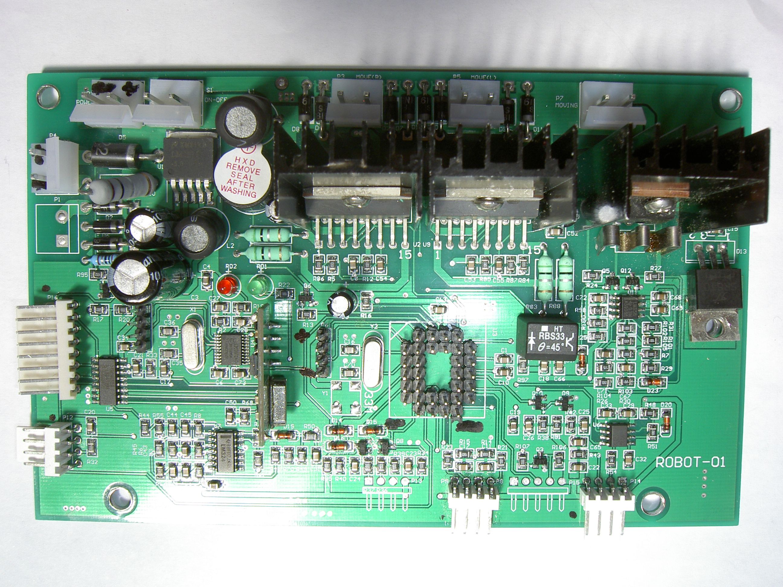
1. TC-G158 technical internals
This section should give you an overall idea of the components present in your mower. It’s good to roughly understand them for your own hacks!
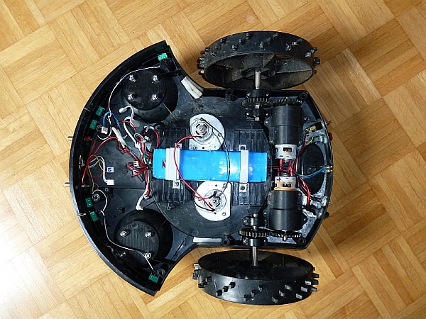
My purchased Tianchen TC-G158 robot mower has the following components:
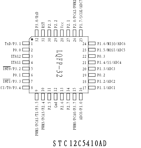
-Main MCU: STC12C5410AD (8051 clone, 10K flash memory, 33 Mhz)
-Hope RF HM 433 Mhz receiver module (for remote control)
-Remote control decoder MCU: STC12C2052AD (sends remote control key data to main MCU, see protocol below)
-Induction unit quad op amp: LM32 (for induction loop inductor amp)
-Optical roll ball sensor: HT RBS33 (theta=45 degree , switches off mowing motor above theta degree)
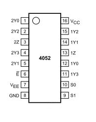
-Dual 4-channel mux/demux: 74HC4052D (to read in induction loop inductors and battery sense/rain sensor)
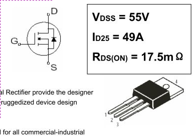
-Power MOSFET: IRFZ44N (for mowing motor)
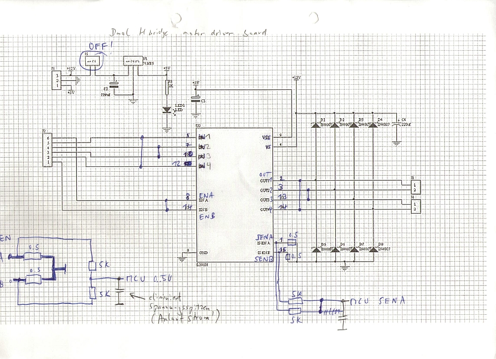
-Full bridge driver: L298N (for the left and right motors) – also see example schematics here
-1A step-down simple switch voltage regulator: LM2575S (for main board voltages)
-Solid state amp: SR840 (for mowing motor)
-Timer: NE555 (for IR modulation?)
-Dual op-amp: LM358 (for induction loop inductor)
–
2. Adding an ultrasonic sensor (Arduino hack)
An ultrasonic distance sensor greatly helps to avoid bumping obstacles (or to drive into shrubberies). We use the HC-SR04 as it’s easy to use (you can find these boards on eBay).
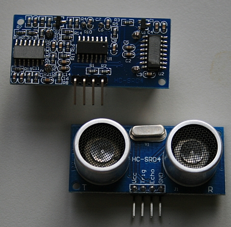
This hack is universal – actually, you can add it to ANY robot mower. The good thing is you can keep the robot’s stock MCU firmware, and it’s easy to add: Just add another two wires to the front bumper push buttons, and your Arduino will simulate one of the bumpers (by switching the bumper signal to LOW) when the ultrasonic distance sensor detects an obstacle!
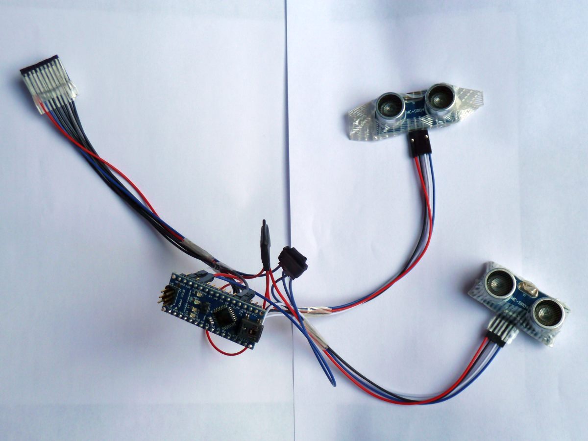
We use an Arduino Nano board for the controller as it’s very popular and very easy to program.
Arduino <—> robot wiring
Pin 7 <—-> robot left bumper signal pin (P8.2, see below)
Pin 8 <—-> robot right bumper signal pin (P8.4, see below)
Pin 12 <—-> ultrasonic board (trigger pin)
Pin 11 <—-> ultrasonic board (echo pin)
VCC <—-> robot +5V (P6.1, see below)
GND <—-> robot GND (P6.4, see below)
Robot bumpers pinout (P8) is (left-to-right):
1-GND
2-left bumper signal pin
3-GND
4-right bumper signal pin
Robot P6 pinout is (top-to-bottom):
1-VCC (+5V)
4-GND
(the first photo shows the version for the Ambrogio L50 robot mower using two ultrasonic sensors)
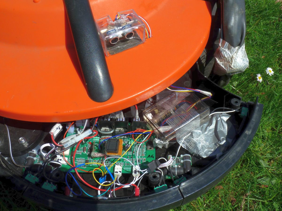
For debugging purpose, you can add a piezo speaker:
Finally, you can see everything in action (NOTE: In this video, there is no perimeter that can stop the robot, it is only the ultrasonic sensor that can stop it)
NOTE: I have not tested yet how the ultrasonic sensor can be automatically deactived when the robot drives into the charging station – I’m not using any perimeter with this robot, so at least it works without perimeter…
For Arduino code, see resources section further below.
Hardware/software used for the hack:
- A microcontroller that is easy to program: I did choose the Arduino Nano for all my hacks. You can find the Arduino Nano controllers on eBay (8-10 EUR)
- Ultrasonic sensor board HC-SR04 – you can find those board on eBay (5-7 EUR)
- he software to develop+flash the Arduino (it’s free/open source):
http://arduino.cc/en/Main/Software
–
3. Replacing the stock MCU firmware (ATMEGA hack)
Replacing the stock MCU firmware requires to write a new firmware, and I did choose the Atmel ATMEGA-168 (on a ready myAVR board MK2 USB) as a replacement for the original 8051 MCU.
The first step is to desolder the MCU socket as you can see on my robot mower board .
Here you can see how I managed to connect my Atmel MCU to the old MCU socket (using some DIY adapter). Alternatively, you can directly connect the individual board pins to your Arduino board using 1-pin-cables (you can find them on eBay).

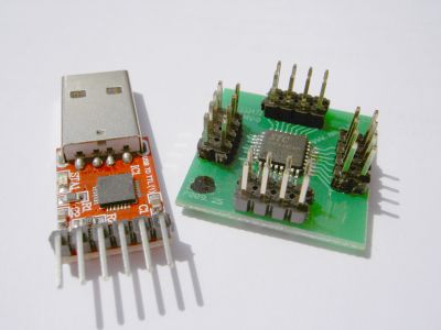
After a while, I noticed that I need something more fancy to upload my new custom software revisions into my mower while sitting comfortable in a chair meters away: a Bluetooth module!
The bluetooth module extends the ordinary ISP RX/TX serial line (RS232) and also allows me to monitor sensor data and robot state changes (and believe me, this feedback is absolutely necessary for debugging your code…)
So this is my final system today:
Original board <==> ATMEGA168 <==> ISP (TTL UART) <==> Bluetooth module <~~> PC (Bluetooth dongle)
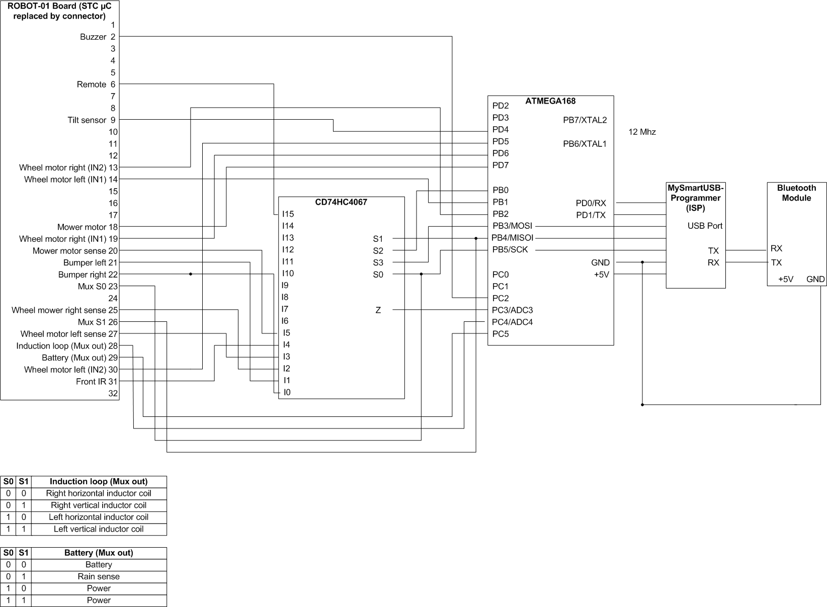
I upload new software builds into the mower via Bluetooth and the serial data of the mower is transmitted via Bluetooth too.
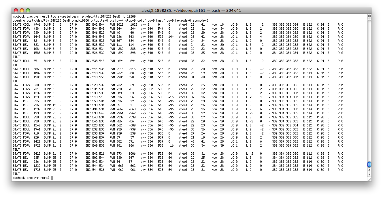
My latest software periodically displays the state of the mower (state, state time, bumper states, IR state, inclination sensor, motor PWM, motor PID controller wxy, motor current, induction coins values, battery state, rain sensor):
All components I needed for this solution:
- myAVR microntroller board – includes mySmartUSB programmer (ISP)
- ATMEGA168 microcontroller (16K flash, operating at 5V)
- 12 Mhz oscillator
- Bluetooth module BTM220 , an inverter 74HCT14N for level shift conversion (because my BTM220 operates at 3.3V, I needed a level shift conversion to 5V)
- RS232 TTL USB module (to configure the Bluetooth module)
- Multiplexer CD74HC4067 (to reduce the number of required pins at the microcontroller)
- Two photo sensors to measure the wheel movement (wheel left/right balance control) – later I replaced this by a declination sensor which works great too
For ATMEGA code, see resources section further below.
–
4. Adding a PID control for the wheels
After purchasing, I noticed the robot has a small problem: when moving from the lower part to the higher part of my garden, it doesn’t move a straight line – it makes circles of 90 degress and less (due to the heavy lead acid batteries my mower is using) …
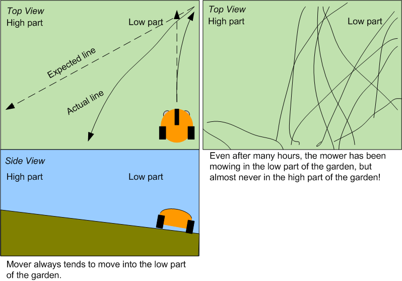
(Also have a look at my mower simulation that demonstrates the difference ‘lawn with and wihtout slope’).
So I decided to add some software PID controller to it to control the left-right wheel balance 🙂 and it solved this specific problem (see videos with and without balance controller).
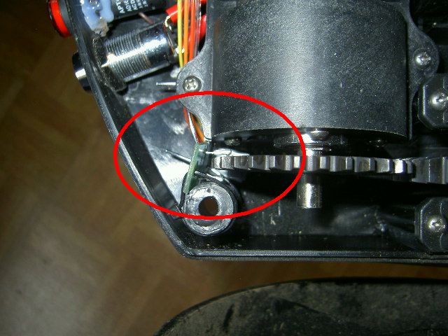
And here you can see how I added photo interruptors (LTH301-07) for the left and right motors to measure the wheel movement (for the left-right wheel balance control):
–
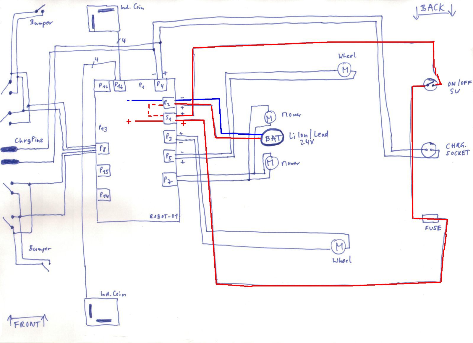
5. Resources (wiring diagram, code etc.)
- Wiring(motors, bumpers, charger, battery etc.)
- Main MCU pin description
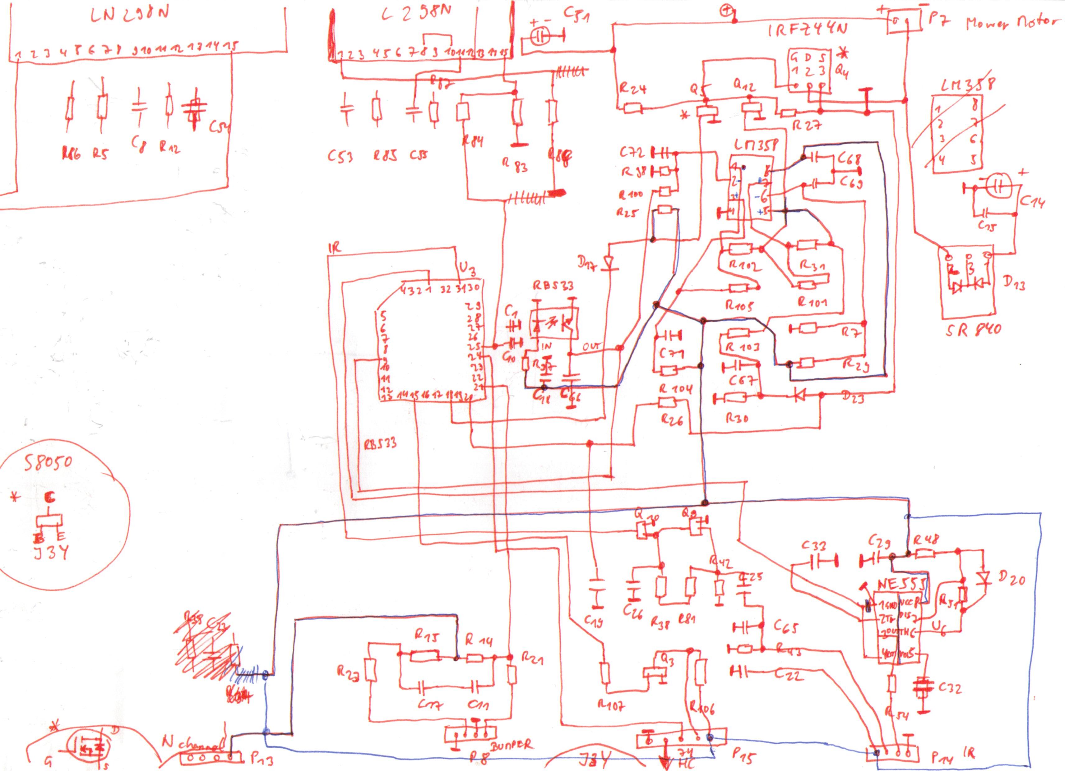
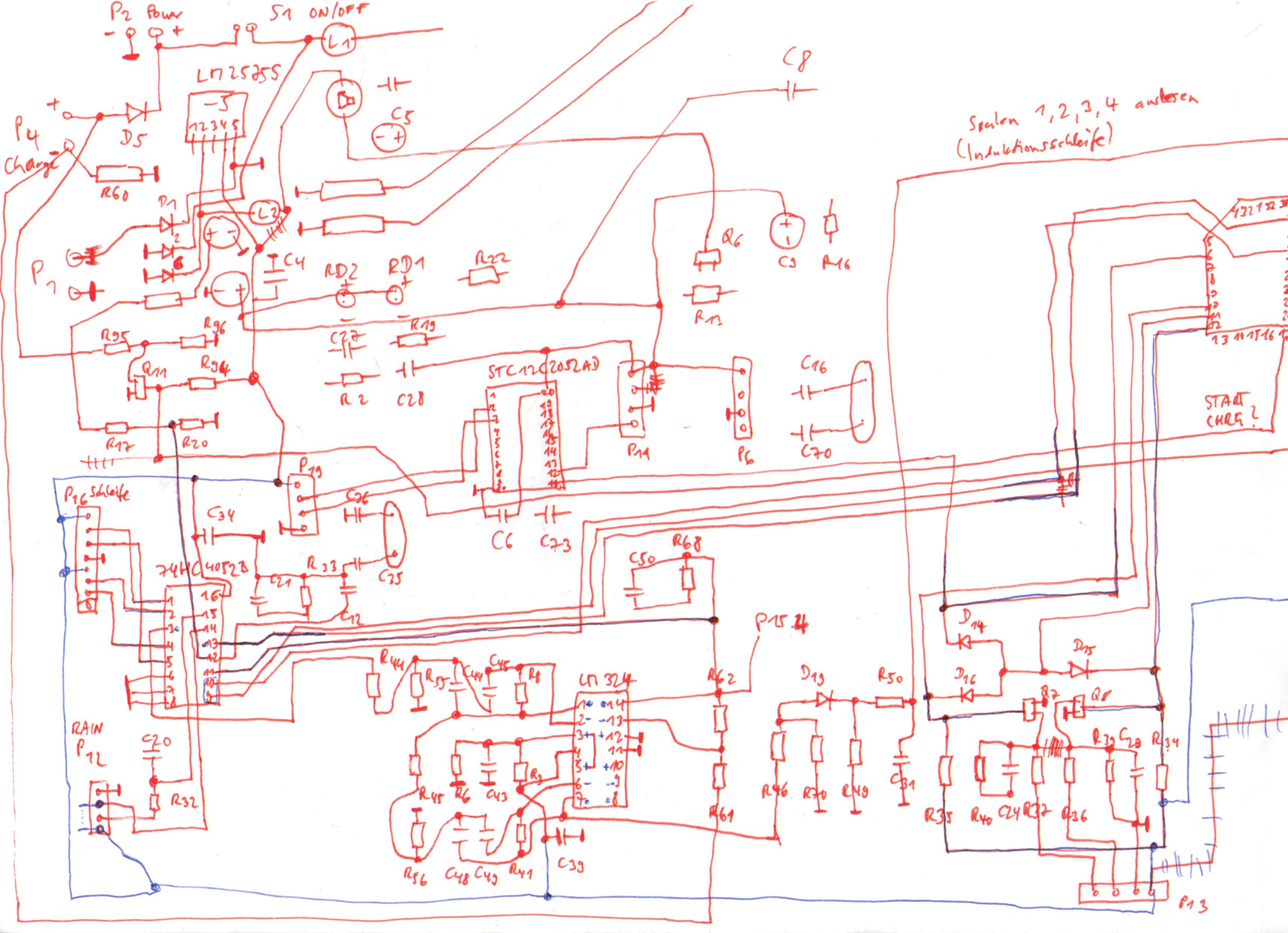
- My pseudo-schematics (1), (2)
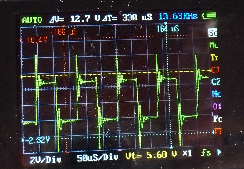
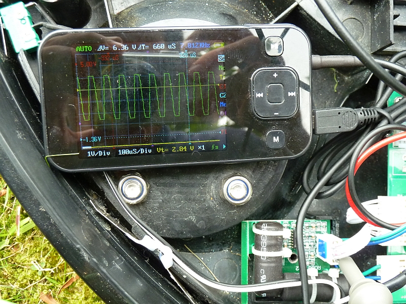
(Warning: always measure and verify using your own board – manufacturers often change their layouts and make adjustments, and without measuring you may damage your own board!) - Charger induction loop signal (measured at induction loop cable output)
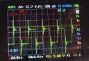
- Induction loop coil signal (measured at induction coil connector)
Connector pinout: +5V, GND, vertical coil output, horizontal coil output
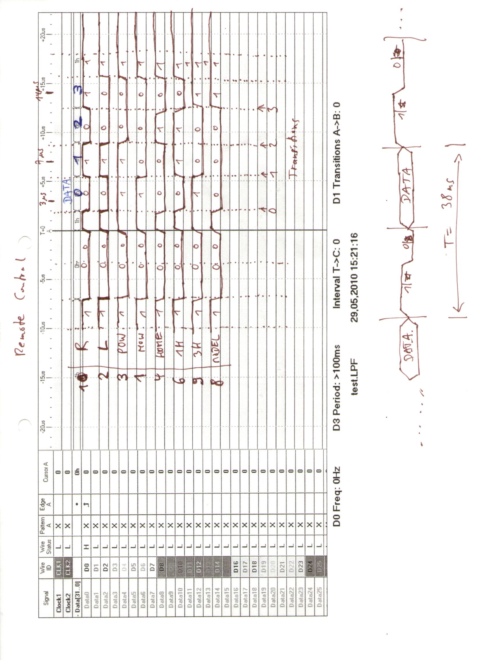
- Remote control protocol
- Robot Mower Ultrasonic Code
- ATMEGA robot mower code (code also describes the MCU socket<->ATMEGA168 wiring – Warning: don’t expect this code to work at once in your own configuration – you’ll need to study schematics, your MCU specifications and much more to get it working!)
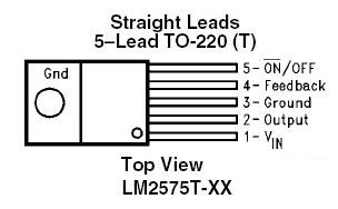
- Pinout of ICs
LM2575S(voltage regulator)
IRFZ44N(N channel power MOSFET)
LM324(operation amplifier)
74HC4052(multiplexer)
L298N (motor driver)
STC12C5410AD(MCU)
STC5406AD (MCU)
–
6. External resources on the Internet
- Wiring diagram for the updated version of the robot (additional security board) which turns-off the mower when the front wheels have no contact
- Induction loop receiver board schematics (and more) at robi2mow
Read your article.. Great work..
I have bought the same robot, but in a newer design, i think..
It is giving me alot of trouble with the HT RBS33 Tilt switch (i think)…
It stop 2 out of 3 times it runs into obstacles (Trees etc).
The Tilt switch in this robot is a 30 degree switch, and i think it is too sensitive.
Do you have any suggestions on how to bypass the switch (I know it is a security issue, but then I will find some other way to check for tilt).
Thanks in advance.
Hi- I think mine did the same with the original software (before I replaced the software by my own) – It sometimes stopped at trees due to the mower’s vibration, and the RBS33 makes a tilt each time, and after several tilts the original software stops the mower.
Idea #1: Make the stops more smoothly for the robot, add some additional obstacles around the trees (sometimes fixed and with a few cm’s). The robot will probably detect them (IR sensor), and then move with slower speed towards them.
Idea #2: Remove the RBS33 from the board, add wires between the RBS33 connectors and the board, and then change the position (degree) of the RBS33 on the board, so that it will not trigger anymore. Requires soldering.
Idea #3: Look for the datasheet of the RBS33 and find out how it internally (electrically) works (I think it’s a transistor at the RBS33 output), and replace it by a transistor. I haven’t examined this in detail, and can do this if you are able to do soldering on your board.
Idea #4: Replace the software by adding your own microcontroller and code 🙂 (Requires that you can program C and some soldering of course).
I hope that some of my answers are useful for you. Let me know if you could solve the problem somhow or to some degree! Regards, Alexander
Regarding the RBS 33, i have a supoman. Almost same motherboard, its using a SMD version of the 12c5401Ad Othervise the same.
I have added a parallel capacitor to the RBS 33, in order to sort the small bumps from when the robot is really tilting.
Hey Alexander
Great project you have made by changing the microcontroller of the robot lawn mover. I got a similar lawn mover (however the controller board have a SMD microcontroller instead), actually I was working on a similar project and was trying to reverse engineer the controller PCB. Then it would be possible to use another microcontroller platform for a better controlling of the robot. Found your blog by incident, but found a lot of your information and discoveries very useful! Thanks a lot!
Best regards
Søren
Hello Søren,
Actually, there is already a project where we did use another micrcontroller (Arduino Mega) connected to the Tianchen board: http://www.ardumower.de
In the downloads there, you can find a file called ‘tcg158.h’ that describes the wiring between Arduino Mega and Tianchen board.
Regards,
Alexander